Figure 17. output sequencing wire interconnect – Vicor Westcor PFC MegaPAC Power Factor Corrected AC-DC Switchers User Manual
Page 31
UG:105
vicorpower.com
Applications Engineering: 800 927.9474
Page 31
5V with "D" option (DC OK)
1
2
3
4
5
6
7
8
3.3V Output
1
12
2
11
3
10
4
9
5
8
6
7
L
1
L
2
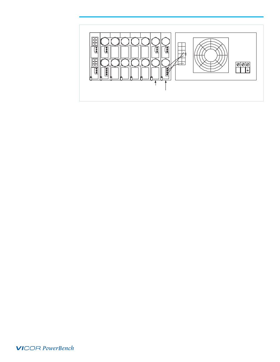
Figure 17.
Output Sequencing
Wire Interconnect
Figure 17 shows the correct wiring connections between the Power Good Connector (J3)
of a 5 V ModuPAC and the Input Interface Connector (J10) of a typical PFC MegaPAC
configuration. In this example, the 3.3 V ModuPAC is located in the slot #7 and the
5 V ModuPAC (with the DC OK option) is located in slot #8. In order for the Power
Good option to properly function, it requires a 5 V source to provide the necessary Vcc
pull up. This 5 V source is conveniently available using the +5 V aux source from the
Input Interface Connector (J10-9 and J10-10). With a Vcc voltage properly applied
to the 5 V ModuPAC's Power Good Connector (J3-1 and J3-4), the Power Good signal
(J3-3) can now be connected to the Enable/Disable control pin for slot #7 (J10-7).
The 5 V ModuPAC's Power Good signal will remain low until its output has reached
approximately 95% of its nominal output voltage. This will keep the 3.3 V output in
disabled mode, allowing the 5 V output to reach regulation first. In addition, should
the 5 V output drop below 85% the Power Good signal will drop low and disable the 3.3
V output. Figures 18 and 19 show the startup and shutdown waveforms for the circuit
shown in Figure 17.