Hinge installation – Therma-Tru SHOP 3 Door Preparation - Book Size User Manual
Page 42
Door
Preparation
3.42
2014 (BOOK SIZE)
Shop 3
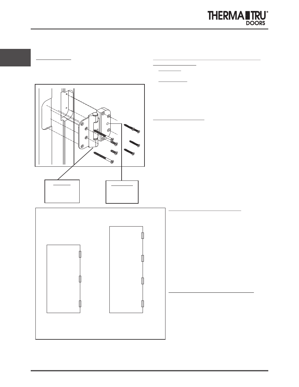
Hinge Installation
Adjustable Hinges
Guide Hinge Shown:
Adjustable Hinge Placement on Door
6/6 to 7/0
height doors
7/10 to 8/0
height doors
Guide
Set
Guide
Guide
Set
Guide
Guide
Vertical Adjustment (Set Hinge)
Horizontal Adjustment (Guide Hinge)
With the door closed or open
. Remove the press-fit Finial Cap from the
bottom of the Set Hinge to expose the
adjustment screw. Use the small
screwdriver for Set Hinges featuring a
plastic Finial Cap. A plastic putty knife is
recommended for Set Hinges featuring a
brass Finial Cap.
Insert the hex wrench into the bottom of
the Set Hinge. Turn the screw clockwise to
raise the panel and counterclockwise to
lower the panel.
Reinstall the Finial Cap.
The door must be open to access the
adjustment screw.
. Insert a 3/16” hex wrench into the
horizontal adjustment screw.
Turn clockwise to decrease the margin
and counterclockwise to increase the
margin on the hinge side.
1
2.
3.
1
2.
Required Tools
1.
2
3.
A 3/16” hex wrench is required.
. A small flat head screwdriver is required.
A plastic putty knife is recommended to prevent
damage to hinge finish.
There are two types of HOPPE Adjustable Hinges
on each door panel:
1.
2.
1.
2.
3.
4.
5.
6.
Set Hinge
Guide Hinge
Assembly Information
: one per panel. The set hinge
provides ± 0.12” vertical adjustment.
: Two or three per panel. The guide
hinges provide ± 0.12” horizontal adjustment.
The two Guide Hinges go in top and bottom
locations with the Set Hinge in the center. For 8’
door the Set Hinge is located second from top of
door. Refer to Figure 2.
Insert the thick side of the hinge into the hinge
mortise on the door.
Pre-drill 3/32” diameter pilot holes through hinge
holes.
Fasten with (4) #8 x 1-1/4” flat head screws refer
to figure 1.
Place hinges into hinge mortise on the frame.
Seat hinge to back of machined hinge pocket.
Fasten with (2) #10 x 3/4” flat head screws in the
middle of each hinge.
Fasten the top & bottom holes with (2) 2-1/2” flat
head screws
Figure 2
Guide Hinge
Horizontal
Adjustment
Set Hinge
Vertical
Adjustment
(Under Finial Cap)
Figure 1