Installation – Regency Liberty L965E Large Gas Fireplace User Manual
Page 33
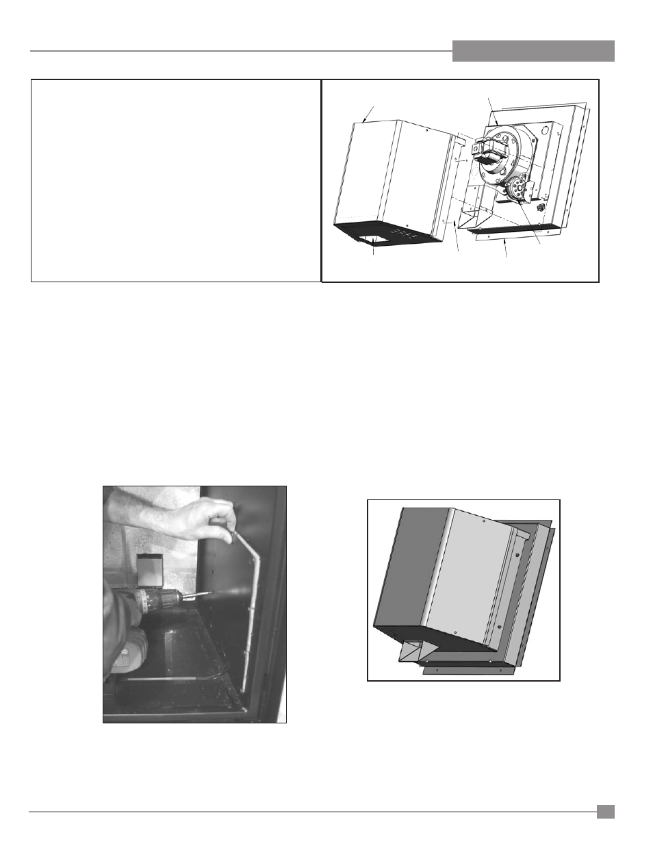
Power Vent
Case Cover
Power Vent
Screw
Vacuum Switch
Power Vent
Assembly
Exhaust
Cut-Out
Figure 11: Install the power vent cover case.
Figure 12: Cover is installed to the power vent
assembly.
Figure 10: Fan and vacuum switch wired.
Figure 13
: Removing Access Cover.
11. Secure the cord to the Power Vent Assembly with the Strain Relief as shown in Figure 9.
12. Connect the wires to the fan, vacuum switch, and ground according to the wiring diagram in Figure 17. Secure the green ground wire as shown in Figure
9. Route the wires as shown in Figure 10 to prevent them from getting pinched.
13. Align the exhaust deflector with the exhaust cut out on the bottom of the power vent cover and install, refer to Figure 8, 11 and 12. Ensure that the rubber
vacuum hose does not kink when installed.
14. Secure the cover to the power vent assembly with screws to the left and right sides of the assembly.
15. Remove the protective cover from the PVK Control Box Velcro and secure the power vent control box to the side as shown in Figure 1a. If the appliance
is a DV62, place the power vent control box inside the control box of the appliance.
Regency L965E / HZ965E Gas Fireplace
33
INSTALLATION