Installation – Regency Liberty L965E Large Gas Fireplace User Manual
Page 24
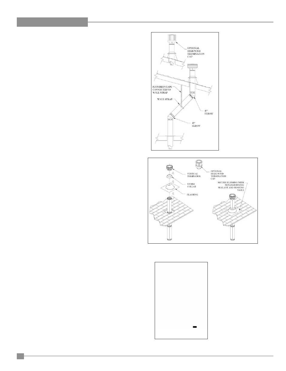
Figure 42: Installation of Flashing & Vertical
Termination.
Figure 41: Vertical
Installation Using High
Wind Cap.
Figure 43: Installation of
Ceiling Fire Stops.
Step 5
. Cut a hole in the roof centered on the small drill hole placed
in the roof in Step 2. The hole should be of sufficient size to
meet the minimum requirements for clearance to combustibles,
as specified earlier. Continue to assemble lengths of Pipe and
Elbows necessary to reach from the Ceiling Firestop up through
the roof line.
Notes:
(1) If an offset is necessary in the attic to avoid obstructions, it is important
to support the vent pipe every 3 feet, to avoid excessive stress on the
Elbows, and possible separation. Wall Straps are available for this
purpose (see Figure 41).
(2) Whenever possible, use 45° Elbows, instead of 90° Elbows. The 45°
Elbow offers less restriction to the flow of flue gases and intake air.
Step 6.
Slip the flashing over the Pipe Section(s) protruding through
the roof. Use a non-hardening sealant between the Flashing
and the roof to prevent water leakage. Secure the base of
the Flashing to the roof with roofing nails. Ensure the roofing
material overlaps the top edge of the Flashing as shown in
Figure 42. Verify that you have at least the minimum clearance
to combustibles at the roofline.
Step 7.
Continue to add Pipe Sections until the height of the Vent Cap
meets the minimum building code requirements described
by your local codes. In the absence of local codes, make
sure the terminal is 2 feet (610mm) above anything within
10 feet (3046mm) of the vent (refer to Figure 44 & Table 5
for clearances for different pitches). Note that for steep roof
pitches, the vent height must be increased. In high wind
conditions, nearby trees, adjoining rooflines, steep pitched
roofs, and other similar factors can result in poor draft, or
down-drafting. In these cases, increasing the vent height may
solve this problem.
Step 8.
Slip the Storm Collar over the Pipe, and push it down to the top
of the Flashing, as shown in Figure 42. Use the non-hardening
sealant above and below the joint between the Storm Collar
and the Pipe.
Step 9.
Twist lock the Vent Cap.
Notes:
(1) For multi-story vertical installations, a Ceiling Firestop is required at
any subsequent floors (as shown in Figure 43). The opening should
be cut and framed in the same manner as the opening in Step 3 (see
Figure 40).
(2) Any occupied areas above the first floor, including closets and storage
spaces, which the vertical vent passes through, must be enclosed.
The enclosure may be framed and sheet rocked with standard
construction materials, however minimum allowable clearances
between the outside of the vent pipe must be maintained. Do not fill
any of the required air spaces with insulation.
24
Regency L965E / HZ965E Gas Fireplace
INSTALLATION