Specifications, Hart, Protocol – Steriflow Mark 16IQ Series User Manual
Page 3
Mark 16IQ Smart Valve Positioners
Specifications
-3-
Input:
•
Signal Range: 2 wire circuit ~ 4-20 mA; 3/4 wire cir-
cuit ~ 0 / 4-20 mA
•
Load Voltage: 2 wire circuit ~ > 11V with HART; > 10
V without HART
•
Auxiliary Voltage: 3/4 wire circuit ~ 18 - 30 V
Output:
Up to full air supply pressure
Pneumatic System:
•
Air Supply Pressure: 45 psig max for Steriflow Valve
actuators)
•
Air Capacity: > 5.3 scfm; adjustable
•
Standard Consumption: 0.02 scfm independent of
air supply pressure
Optional Gauge Block:
delivered with two gauges for in-
put air supply and positioning pressure
Control Data:
•
Sensing Time A/D Converter: 12.5 ms
•
Resolution A/D Converter: <0.05%
•
Transmission Error A/D Converter: <0.2%
•
Dead Band Controller: adaptive or adjustable, 0.1-
10%
•
Setting Time Controller: 1.5 - 150
Ambient Temperature:
-20 to +175°F
Shock Resistance:
10g
Connections:
•
Pneumatic: 1/4" NPT
•
Electric: screwed terminals max. 1.5mm2, cable
union size PG 13
Protection Class:
IP 65/NEMA 4X
Weight:
2.86 pounds
Hazardous Location Approvals:
•
Basic unit: none
•
Standard HART
®
protocol unit:
—
FM/CSA: (IS) Class I, Div. 1, Groups ABCD, T6/
T5/T4
–
NEC 505: Class I, Zone 2 Group IIC T6/
T5/T4.
–
NEC 500: Class I, Div 2 Group IIC T6/T5/
T4.
—
EU: II 2G EEx ia/ib IIC T6/T5/T4
•
For explosion proof installations (i.e. (XP) Class I,
Div. 1), please contact factory for options.
With the HART
®
option comprehensive sets of mainte-
nance and diagnostic data can be called up directly at
the positioner itself:
•
zero point and range
•
actuating speed
•
original & current stats
—
Actuator leakage
—
Operating hours
—
Min/max temperatures
—
Valve limit position (i.e. change of stroke length
due to seat wear)
•
dead band in both directions
•
number of alarm reports
•
number of directional changes
•
total travel
In addition, you may call up data about the controlled ac-
tuator:
•
instrument number
•
type of actuator
•
operating mode
•
process data
•
parameter data
With the SIPROM PS2 Software interface, the current
maintenance data can be remotely compared with previ-
ous information to quickly detect any deviations so that
corrective action can be taken. And, actuator and valve
problems can be caught early to allow ample time to
schedule repairs.
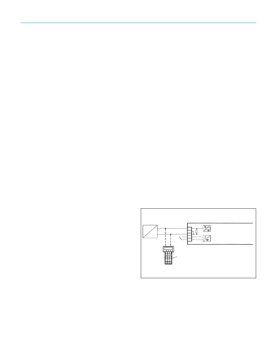
HART
®
Protocol
Positioner
Digital Input 1
HART Communicator
J
Two-Wire Connection
+ 4 to 20 mA
How to Order
1. See Mark 978 Control Valve order grids
2. Select the appropriate base valve model. See mod-
els Mark978SP or NSP for an Inline valve. (Sp for Side
Mounted Positioner).
3. Select the specific positioner you want in the last digit
of the MK978 model number. Choices are available
for HART
®
, Foundation Fieldbus
TM
, models.