Steriflow JSRLFLP Series User Manual
Page 7
F
low
D
ata
For
c
v
trim
selection
-7-
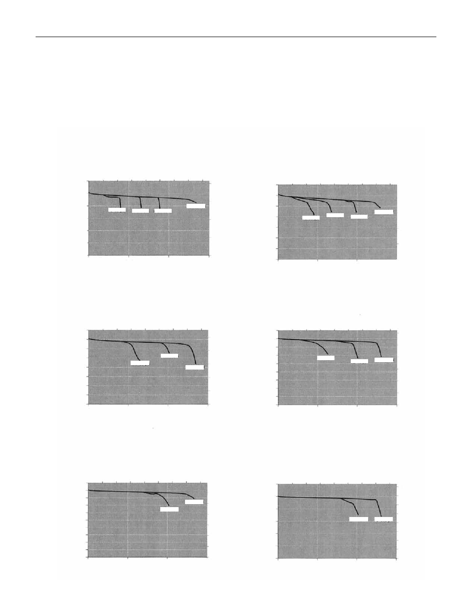
The graphs illustrate the change or "droop" in outlet pressures as the flow rate increases, and the lockup (setpoint rise) as flow
decreases and approaches zero.
Flow Coefficient: 0.012
Maximum inlet pressure: 150 psig (10,3 bar)
Pressure Control Range
Range Spring: 0-75 psig (0-5,2 bar)
Set Point: 45 psig
Pressure Control Range
Range Spring: 0-75 psig (0-5,2 bar)
Set Point: 35 psig
Pressure Control Range
Range Spring: 0-75 psig (0-5,2 bar)
Set Point: 25 psig
Pressure Control Range
Range Spring: 0-75 psig (0-5,2 bar)
Set Point: 30 psig
Pressure Control Range
Range Spring: 0-75 psig (0-5,2 bar)
Set Point: 40 psig
0.5
0
1
1.5
2
2.5
3
0
1
0
1
2
30
25
20
15
10
5
0
1.5
0
0
Outlet Pressure (psi)
Outlet Pressure (psi)
Outlet Pressure (psi)
Outlet Pressure (psi)
Outlet Pressure (psi)
Outlet Pressure (bar)
Outlet Pressure (bar)
Outlet Pressure (bar)
Outlet Pressure (bar)
Air Flow (L/min)
Air Flow (L/min)
Air Flow (L/min)
Air Flow (L/min)
Air Flow (SCFM)
Air Flow (SCFM)
Air Flow (SCFM)
Air Flow (SCFM)
Air Flow (SCFM)
1.5
15
10
5
20
30 35 40
0
0.5
0
2
1
2.5
0
0
30
25
20
15
10
35
40
45
50
P1=75 psi
P1=100 psi
P1=75 psi
P1=100 psi
P1=100 psi
P1=75 psi
P1=100 psi
P1=35 psi
P1=50 psi
P1=75 psi
P1=100 psi
0.5
1
1
1.5
0.5
Air Flow (L/min)
0.5
35
30
25
20
15
10
0
5
40
1.5
1.5
0
0
JSRLFLP S
eRieS
L
ow
F
Low
L
ow
P
ReSSuRe
R
educing
V
aLVe
25
P1=50 psi
P1=35 psi
P1=50 psi
15
10
5
20
30 35 40
25
15
10
5
20
30 35 40
25
P1=75 psi
0.5
15
10
5
20
30 35 40
25
15
10
5
20
30 35 40
25
15
10
5
20
30 35 40
25
0.5
0
1
1.5
2
2.5
3
0.5
0
1
1.5
2
2.5
3
0.5
1
1.5
0
0.5
1
1.5
35
30
25
20
15
10
0
5
40
45
P1=50 psi
Outlet Pressure (bar)
1
2
1.5
0.5
3.5
4
Outlet Pressure (bar)
Air Flow (SCFM)
Air Flow (L/min)
Pressure Control Range
Range Spring: 0-75 psig (0-5,2 bar)
Set Point: 50 psig
P1=100 psi
P1=75 psi
0
20
10
30
40
50
60
Outlet Pressure (psi)
1
1.5
0.5
35
30
25
20
15
10
5