Skyjacker FAA301 User Manual
Page 5
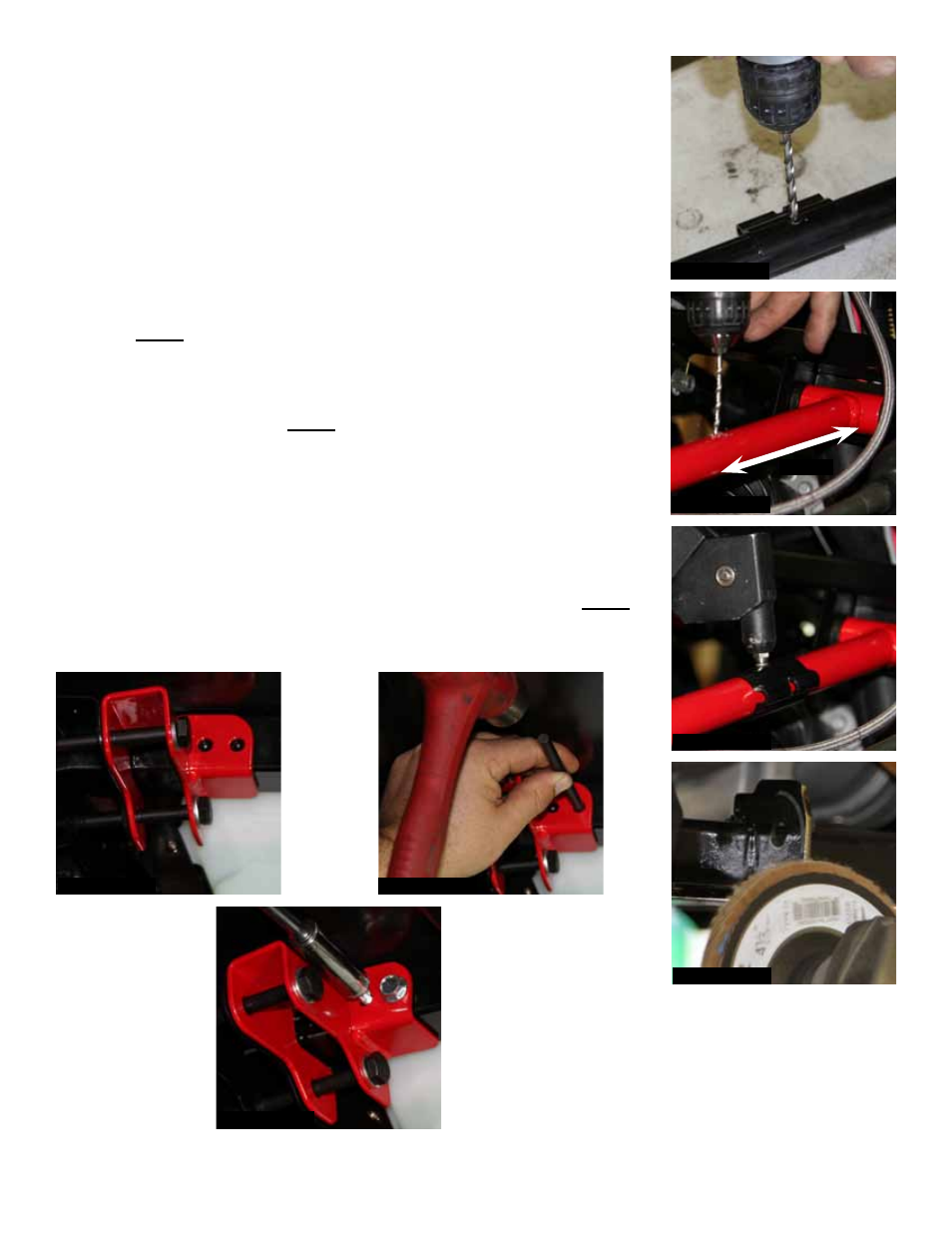
24. Remove the brake line retaining bracket from each OEM upper A-arm
using a 5/32” drill bit to remove the rivet head. (See Photo # 17)
25. Measure from the rearward eyelet of each new Skyjacker upper
A-arm 5 1/6”. Mark, center punch, & drill each new brake line retaining
bracket mounting location using a 5/32” drill bit. (See Photo # 18)
26. Install an OEM brake line retaining bracket to each new Skyjacker
upper A-arm using the supplied 5/32” rivets. (See Photo # 19)
27. Refer to the marked lines made on the front lower A-arm mounting
tabs in Step # 9 & grind to the outer edge of these previously marked
lines.
Note: Be careful not to damage the cv-boots. (See Photo # 20)
28. Install the new Skyjacker upper shock brackets to the OEM upper
shock brackets using the supplied 10mm x 100mm bolts, washers,
nuts, & a 17mm socket.
Note: Do not tighten at this time. (See Photo
# 21)
29. Mark, center punch, & drill the new frame mounting locations for the
new Skyjacker upper shock brackets using a 1/4” drill bit. (See Photo
# 22)
30. Attach each new Skyjacker upper shock bracket to the frame using
the supplied 5/16” x 3/4” thread cutter bolts & a 1/2” socket.
Note: Do
not tighten at this time. (See Photo # 23)
I-FAA301
Pg 5
Photo # 17
5 1/6"
Photo # 18
Photo # 19
Photo # 20
Photo # 21
Photo # 22
Photo # 23