Using counters – SATEC RDM172 Manual User Manual
Page 76
Chapter 4 PAS Application Software
General Meter Setup
76
Series PM172 Powermeters
Option Range
Description
Output
parameter
See Appendix B
Selects the measured parameter to be transmitted
through the analog output channel.
Zero scale
Defines the low engineering scale (in primary units)
for the analog output corresponding to a lowest
(zero) output current (0 or 4 mA)
Full scale
Defines the high engineering scale (in primary units)
for the analog output corresponding to a highest
output current (1 or 20 mA)
Before entering the setup dialog, ensure that you selected the correct analog
current option for your expander on the Instrument Setup tab in the
Tools/Configuration dialog. For scaling output parameters, see
“Programming Analog Outputs” above.
Ì
Analog expander outputs are not operational until you globally enable the analog
expander option in your meter through the Device Options menu.
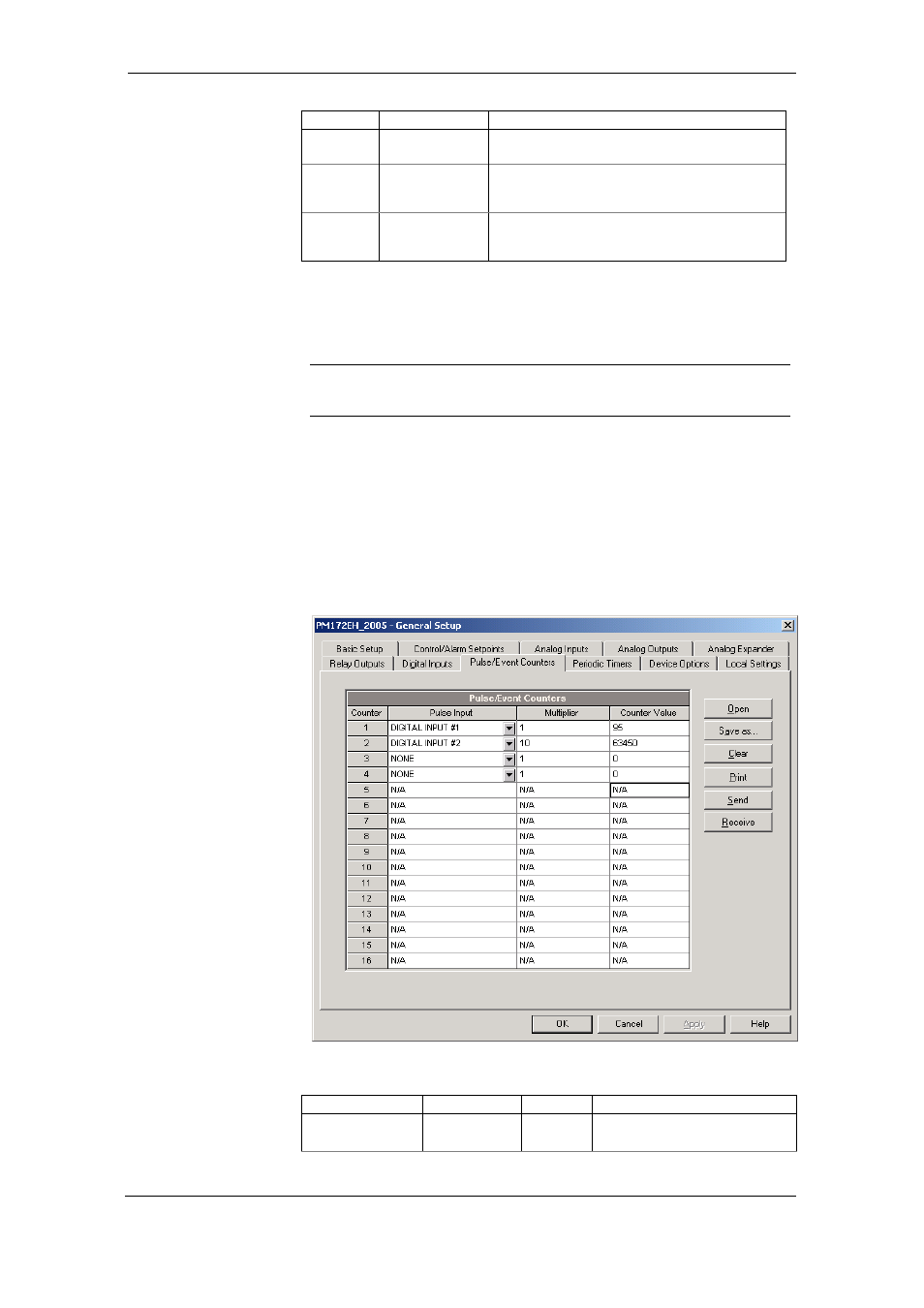
Using Counters
The meter provides four six-digit counters that count different events.
To configure the device counters, select General Setup from the Meter Setup
menu, and then click on the Pulse/Event Counters tab.
Each counter is independently linked to any digital input and count input
pulses with a programmable scale factor. Each counter can also be
incremented in response to any internal or external event, checked and
cleared through the Control Setpoints.
The following table lists available options.
Option Range
Default Description
Pulse Input
None,
DI1-DI2
None
Links a digital input to the counter