Operation of the terminal – Opticon PHL 1300 User Manual
Page 15
U
SER
’
S MANUAL
PHL1300
TERMINAL
/ IRU1300
CRADLE
15
The functionality of the terminal is determined
by software, the so-called user application,
that is running on the terminal.
Usually, the terminal is not equipped with
software and has no functionality. At first the
user application must be loaded before the
terminal can be used for barcode scanning.
Tools for developing a user application on the
PC for use on the terminal, as supplied by
Opticon are:
Application Generator
PotStar (Limited or Professional)
C language: Microtec ANSI-C compiler
and C library for handheld terminals.
The user application must be downloaded
from the PC into the terminal. You can use the
cradle or an infrared adapter for communication
between the terminal and the PC. A program
on the PC will send the user application to the
terminal, where it is stored in FlashROM
memory.
When the functionality of the terminal is defined
by the application it is ready for operation.
In a typical application you will press the trigger
key and scan a bar code label as described in
the next chapter. Scanned data and data
entered from the keyboard is stored in the
terminal's RAM. The user application can use
this data in subsequent steps.
The collected data can be transmitted to the PC
for further processing through the cradle.
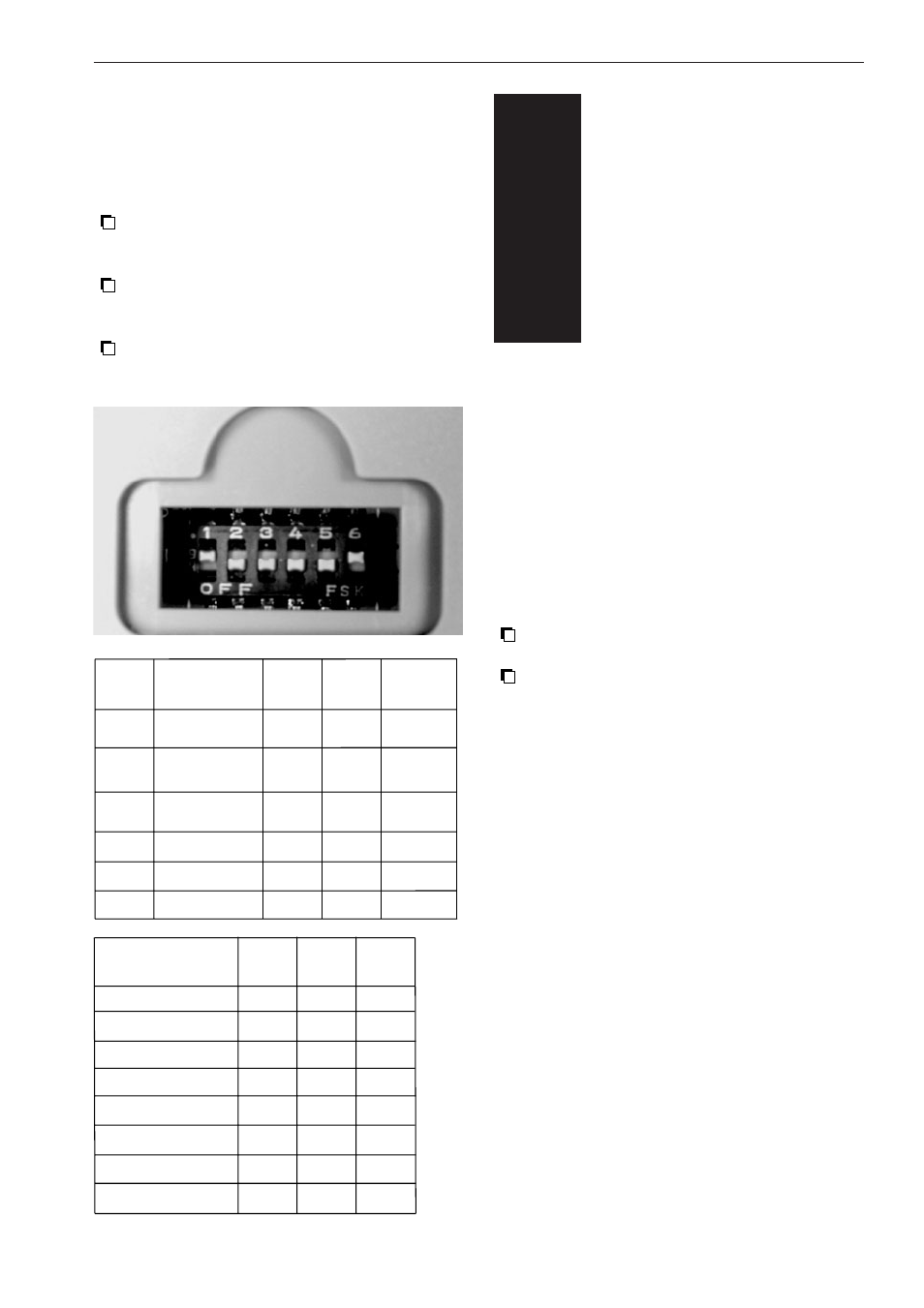
2.6.3 DIP switch settings on cradle
Setting the DIP switches on or off will result in
differrent baudrates and enabled or disabled
functions of the cradle.
Open the cover of the DIP switches on the
bottom of the cradle in order to reach the
DIP switches.
Turn the DIP switch ON by moving it
upwards into the direction of the dipswitch
number.
Turn the DIP switch OFF by moving it
downwards into the direction
OFF
.
FUNCTIONS
RS 232
CONNECTION
RS485
TERMINATOR
RS485
TERMINATOR
BAUDRATE *
BAUDRATE *
BAUDRATE *
ON
in use
in use
in use
--
--
--
OFF
not
in use
not
in use
not
in use
--
--
--
DIP
SWITCH
SW 1
SW 2
SW 3
SW 4
SW 5
SW 6
SW
4
OFF
ON
OFF
ON
OFF
ON
OFF
ON
SW
5
OFF
OFF
ON
ON
OFF
OFF
ON
ON
SW
6
OFF
OFF
OFF
OFF
ON
ON
ON
ON
* )
BAUDRATE
1200
2400
4800
9600
19200 (default)
38400
115200
AUTO (PC controlled)
DEFAULT
ON
OFF
OFF
OFF
OFF
ON
OPERATION OF
THE TERMINAL
3
3