MTS SWIFT 50 GLP Sensor User Manual
Page 63
Road Simulator
SWIFT 50 GLP Sensors Installation
Installing the Transducer
63
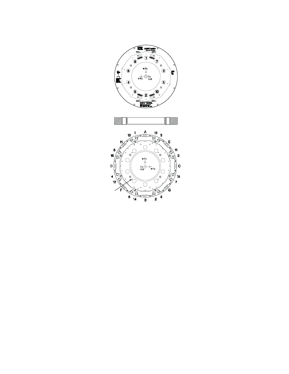
Bolt Torque Sequence
7. Install the vehicle on the road simulator.
Refer to the instructions in your road simulator operation manual.
8. Attach the connector housing (or the slip ring bracket and slip ring) to each
transducer.
9. Attach the appropriate cables from the connector housing or one cable from
the slip ring to the TI or data acquisition.
A.
Connect the cable from the Load connector on the connector housing,
or from the slip-ring connector, to the transducer connector on the slip-
ring daughter board of the TI box(es).
B.
If used, connect the cable from the Accel connector on the connector
housing to your data acquisition device.
C.
Connect the cables from the Shunt A and Shunt B connectors on the
connector housing or the slip-ring bracket to the Shunt A and Shunt B
connectors on the TI box(es)
Connector Side
S50-47
329 Simulator and Hub Mount Side
1 through 10 = M22
(modified lug nuts)
A through H = M10 bolts
1 through 16 = M16 bolts
M5 Threaded
Holes (4)
- Series 111 Accumulator (40 pages)
- Series 249G2 Swivels (34 pages)
- Series 201 Actuators (40 pages)
- Series 215 Rotary Actuator (68 pages)
- Series 242 Actuators (40 pages)
- Series 244 Actuators (68 pages)
- Series 247 Actuators (40 pages)
- Series 248 Actuators (46 pages)
- 709 Alignment System (158 pages)
- Series 609 Alignment Fixture (70 pages)
- 494 Controller Hardware FT 40 (344 pages)
- ReNew Technical Reference (50 pages)
- DCPD Measurement System (46 pages)
- Bionix EnviroBath (40 pages)
- FGW900 High-temperature Furnace (38 pages)
- Model 409.83 Temperature Controller (40 pages)
- Series 651 Environmental Chambers (30 pages)
- Series 653 High-Temperature Furnaces (38 pages)
- Series 658 Environmental Chamber (24 pages)
- Series FEC Environmental Chamber (48 pages)
- Model 685.53 Grip Control Module (24 pages)
- Series 685 Hydraulic Grip Supply (48 pages)
- Bend Fixture-10 kN (2 pages)
- Grip-Manual Bend Fixture-100 kN (2 pages)
- Grip-Manual Bollard-2 kN (2 pages)
- Grip-Manual Bollard-500 N (2 pages)
- Compression Platen-100 kN-100mm (2 pages)
- Compression Platen-100 kN-150mm (2 pages)
- Compression Platen-100 kN-200mm (2 pages)
- Compression Platen-20 kN (2 pages)
- Compression Platen-20 kN-100mm (2 pages)
- Compression Platen-20 kN-200mm (2 pages)
- Compression Platen-20 kN-SST (2 pages)
- Compression Platen-500 N FYC502A (2 pages)
- Compression Platen-500 N FYB502A (2 pages)
- Compression Platen-500 N-50mm (2 pages)
- Grip-Pneumatic Vise-Style-1 kN (2 pages)
- Pneumatic Bollard-500 N (2 pages)
- Scissor-Style-2 kN (2 pages)
- Scissor-Style-5 kN (2 pages)
- Screw-Style-5 kN (2 pages)
- Screw-Style-5 kN-SST (2 pages)
- Bend Fixture-1000 kN (2 pages)
- Bend Fixture-300 kN (2 pages)
- Bolt Grips (32 pages)