MTS SWIFT 50 GLP Sensor User Manual
Page 41
Road and Track Vehicles
SWIFT 50 GLP Sensors Installation
Installing the Transducer
41
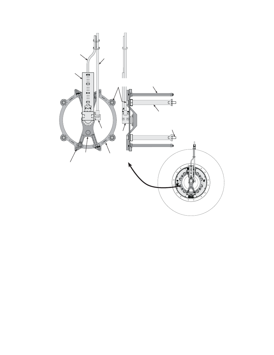
D.
Secure the top plate to the standoffs using the four M12 bolts and
washers.
Lubricate the threads with Molykote g-n paste and torque to 93 N•m
(69 lbf•ft).
E.
Install the slip-ring bracket with the slip ring, conduit bracket, and
restraint tube.
Slide the restraint tube through the hole in the anti-rotate bracket
(installed earlier) as far as necessary to align the slip-ring bracket to the
connectors on the top plate.
The slip-ring bracket fits over the 9-pin connectors on the top plate at
the locations labeled Board A and Board B. The slip-ring bracket is
similarly labeled to prevent connecting it the wrong way.
Standoffs (4)
Top Plate
Slip-Ring
Bracket
M12 Threaded
Studs (4)
Extension
Brackets (4)
S50-40
M12 Bolts (4)
and Washers
Anti-rotate
Hinge
Assembly
Tube
Cable
Cable
Conduit
Bracket
Slip
Ring
Hinge
M8 Bolts (4)
- Series 111 Accumulator (40 pages)
- Series 249G2 Swivels (34 pages)
- Series 201 Actuators (40 pages)
- Series 215 Rotary Actuator (68 pages)
- Series 242 Actuators (40 pages)
- Series 244 Actuators (68 pages)
- Series 247 Actuators (40 pages)
- Series 248 Actuators (46 pages)
- 709 Alignment System (158 pages)
- Series 609 Alignment Fixture (70 pages)
- 494 Controller Hardware FT 40 (344 pages)
- ReNew Technical Reference (50 pages)
- DCPD Measurement System (46 pages)
- Bionix EnviroBath (40 pages)
- FGW900 High-temperature Furnace (38 pages)
- Model 409.83 Temperature Controller (40 pages)
- Series 651 Environmental Chambers (30 pages)
- Series 653 High-Temperature Furnaces (38 pages)
- Series 658 Environmental Chamber (24 pages)
- Series FEC Environmental Chamber (48 pages)
- Model 685.53 Grip Control Module (24 pages)
- Series 685 Hydraulic Grip Supply (48 pages)
- Bend Fixture-10 kN (2 pages)
- Grip-Manual Bend Fixture-100 kN (2 pages)
- Grip-Manual Bollard-2 kN (2 pages)
- Grip-Manual Bollard-500 N (2 pages)
- Compression Platen-100 kN-100mm (2 pages)
- Compression Platen-100 kN-150mm (2 pages)
- Compression Platen-100 kN-200mm (2 pages)
- Compression Platen-20 kN (2 pages)
- Compression Platen-20 kN-100mm (2 pages)
- Compression Platen-20 kN-200mm (2 pages)
- Compression Platen-20 kN-SST (2 pages)
- Compression Platen-500 N FYC502A (2 pages)
- Compression Platen-500 N FYB502A (2 pages)
- Compression Platen-500 N-50mm (2 pages)
- Grip-Pneumatic Vise-Style-1 kN (2 pages)
- Pneumatic Bollard-500 N (2 pages)
- Scissor-Style-2 kN (2 pages)
- Scissor-Style-5 kN (2 pages)
- Screw-Style-5 kN (2 pages)
- Screw-Style-5 kN-SST (2 pages)
- Bend Fixture-1000 kN (2 pages)
- Bend Fixture-300 kN (2 pages)
- Bolt Grips (32 pages)