MTS SWIFT 50 GLP Sensor User Manual
Page 38
SWIFT 50 GLP Sensors Installation
38
Road and Track Vehicles
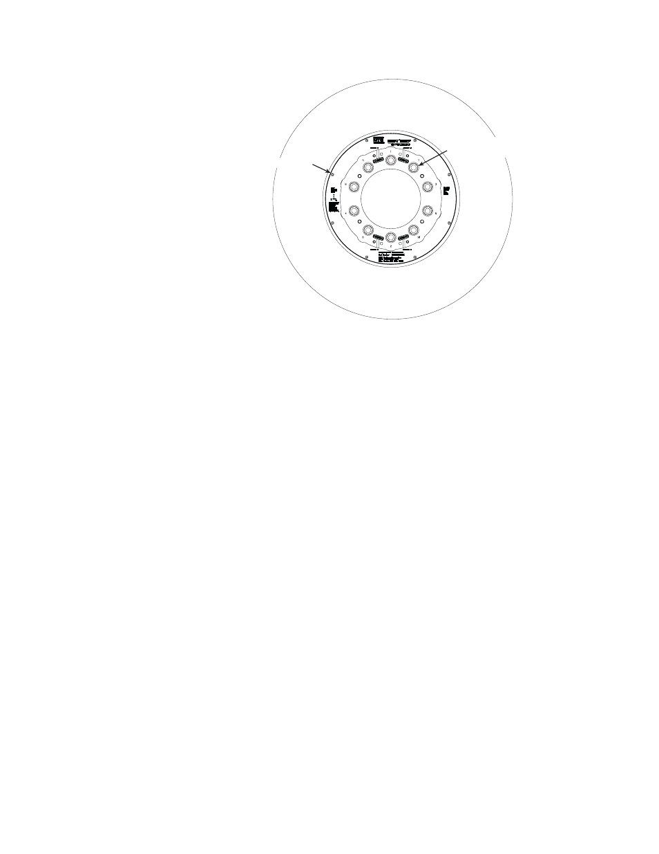
Installing the Transducer
3. If necessary, assemble the cable conduit brackets and hinge base with anti-
rotate tube onto the slip ring. See the next figure.
Note
Typically this step is only required for new slip rings. After the assembly
is complete, there should be no need to disassemble it except if a
component becomes damaged.
A.
Connect the cable to the slip ring.
B.
Wrap the slip-ring connector and cable connector with butyl rubber
shrink tape (MTS part number 100-175-781 or equivalent).
Cut approximately 150 mm (6 in) of tape from the roll.
Remove the backing from the tape.
Stretch the tape until it is approximately 1/2 of its original width.
Begin by putting two wraps of tape tightly around the slip ring
connector and cable connector.
Continue wrapping up the connector and cable approximately 150 mm
(6 in). Overlap the tape by approximately 1/2 of its width.
C.
Install the cable conduit bracket onto the slip ring and secure the left
side with the four M5 X 0.8 mm fasteners.
Lubricate the fasteners with Molykote g-n paste and torque to 6.5 N•m
(56 lbf•in).
5
4
3
6
9
7
8
10
2
1
S50-41
Modified
Lug Nuts (10)
Transducer