MTS SWIFT 50 GLP Sensor User Manual
Page 37
Road and Track Vehicles
SWIFT 50 GLP Sensors Installation
Installing the Transducer
37
2. Attach the wheel/transducer to the test vehicle.
Installing the lug bolts directly against the transducer face, without the anti-
galling compound and the shim washers, can cause galling of the
transducer face.
Galling of the transducer face can result in uneven torquing (and possible
over-torquing) of the lug bolts.
To prevent galling, always use the shim washers provided. Always lubricate the
bolts and shim washers as described below.
Lubricate the lug bolt threads, under the bolt head, and both faces of the
shim washers with the Nikal based anti-galling compound.
Tighten the lug nuts in 203 N•m (150 lbf•ft) increments, in the sequence
shown in the next figure to the torque rating recommended for the wheel.
Important
Do not exceed a torque of 815 N•m (600 lbf•ft).
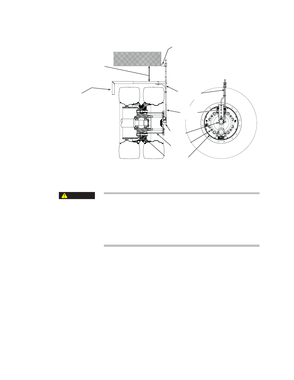
Ensure bracket will not hit
body parts during vehicle
testing or jouncing.
Slip Ring
Slip-Ring
Extension
Bracket
For dual or nonsteering axles, the
anti-rotate arm must be mounted
to the unsprung mass or
suspension, or possibly the fender
or trailer (less desireable).
If the arm is mounted to the fender
or trailer, the assembly must have
a close-fitting hole that will
accommodate the suspension
jounce travel.
The bracket can be attached to
the brake caliper if wheel hub
assembly is equipped with disc
braking system.
If the anti-rotate bracket is
fender or trailer-mounted, it
must be in a vertical orientation
so that when the vehicle
jounces the anti-rotate arm does
not rotate and cause errors in
the data or bend the rod.
The anti-rotate arm must be
long enough to accommodate
vehicle jounce.
S50-45
Dual Wheel Slip Ring and Anti-Rotate Assembly
Transducer
Anti-Rotate
Assembly
Cable
Conduit
Bracket
CAUTION