MTS SWIFT 50 GLP Sensor User Manual
Page 40
SWIFT 50 GLP Sensors Installation
40
Road and Track Vehicles
Installing the Transducer
C.
Make sure that the covers on the shunt connectors are in place and
secure.
Press the covers over the shunt connector. Secure the covers by
tightening the two SST 10-32 UNF screws (one for each cover), using
an M4 or 5/32 inch hex key wrench, to 3.8 N•m (2.8 ft-lbf).
5. For dual rim configurations (see the next figure): Attach the extension
assembly and slip-ring bracket with slip ring to the transducer.
A.
Thread the standoffs, with the M12 threaded studs, into the four M12
threaded holes in the face of the transducer.
Lubricate the threads on each threaded stud with Molykote g-n paste
and torque to 93 N•m (69 lbf•ft).
B.
Attach the four extension brackets to the top plate using the M5 X 10
mm long fasteners provided (2 fasteners each).
Orient the short side of the dovetail on the connector toward the center
of the top plate.
Lubricate each fastener with Molykote g-n paste and torque each to 6.5
N•m (58 lbf•in).
C.
Place the top plate, with extensions attached, over the standoffs.
Orient the top plate such that the Board A extension (see the labeling
on the top plate) is aligned with the Board A connector on the
transducer.
Note
Use care when installing the top plate and extensions. The 9-pin
connectors are keyed. The top plate and extensions should be fitted on
straight (without bending or angling it) to make sure they engage the four
connectors simultaneously and evenly.
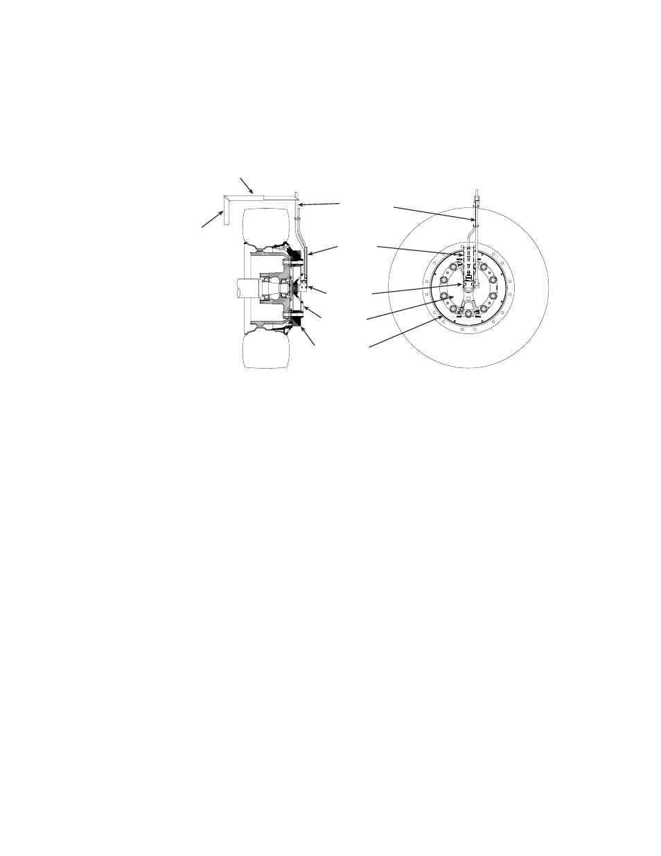
For front or steering axles,
anti-rotate arm must be
mounted to a part of the
unsprung suspension that
steers with the tire, such as
the brake caliper.
Front Wheel Slip Ring and Anti-Rotate Assembly
Anti-Rotate Bracket
(customer supplied)
Anti-Rotate
Assembly
Slip Ring
Slip-Ring
Bracket
S50-44
Transducer
Cable
Conduit
Bracket