Panel installation, Hemming detail – Metal Sales Image II Installation User Manual
Page 20
© Metal Sales Manufacturing Corporation / Subject to change without notice, effective 6/2011
20
Panel Installation
Note: Moisture Barriers, Eave, Valley, and Offset Cleat flashing
must first be installed before panel installation can begin Image II
panels are installed from left to right or right to left.
1. Install Eave flashing and Valley flashing as shown on pages
16-17.
2. Apply a row of Double Bead Tape Sealant on the bottom leg of
the Offset Cleat and align on substrate.
3. Fasten Offset Cleat to substrate with a #8-18 x
3
/
4
"
Truss Head
Woodscrew through top of Eave flashing and into substrate,
1' o.c. Make sure Offset Cleat is lined up to properly accommo-
date hemmed panel.
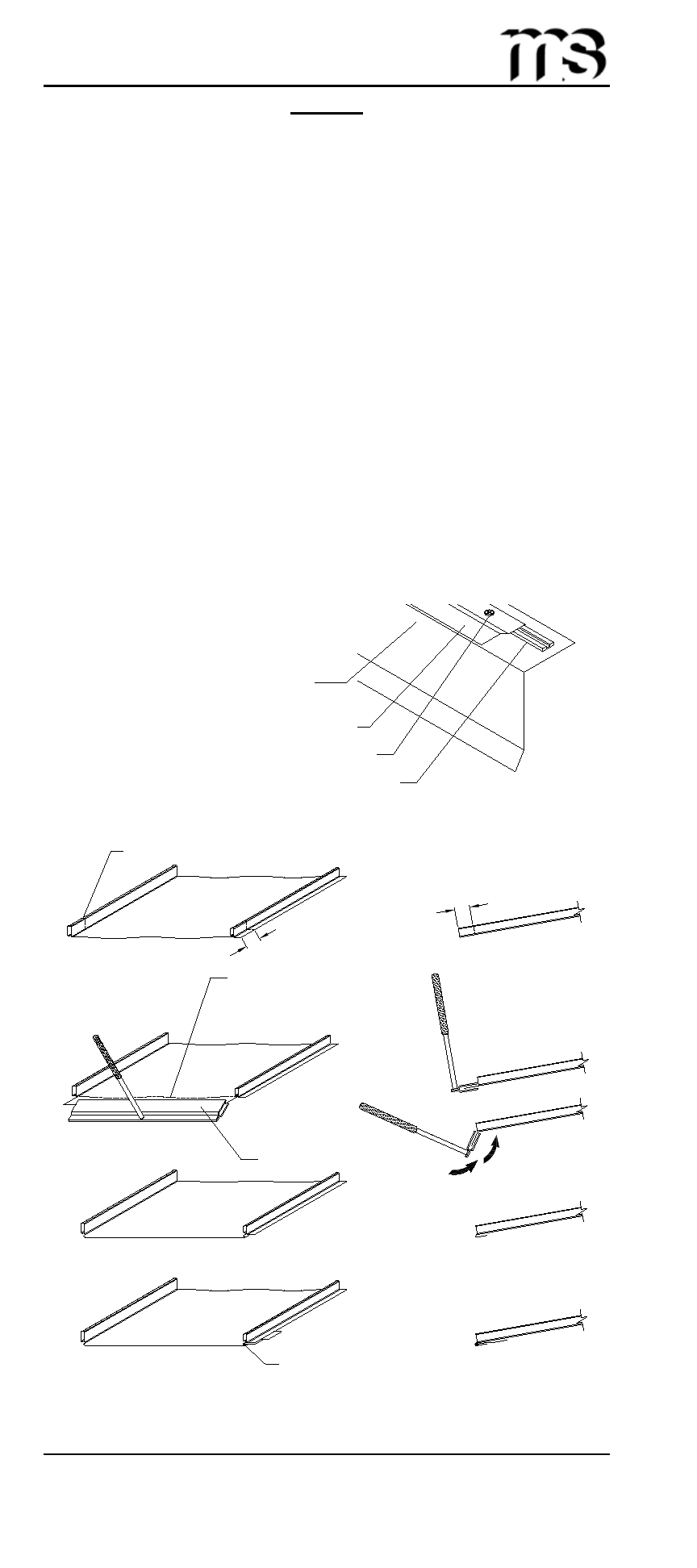
4. Field notch and hem the Image II panel as shown below.
5. Apply a single bead of tube sealant inside the open hem of the
Image II panel.
Note: If you are to field bend the panel ends to close off panels on
the low side, see page 22 before field notching and hemming of the
panels.
Double Bead Tape Sealant (2)
Truss Head Woodscrew (4)
Offset Cleat (3)
Hemming Detail
Field Notch Rib (5)
1
1
/
2
"
1
1
/
2
"
Field bend flat part
of panel to accept
Offset Cleat (6)
Hemming Tool
Field apply tube sealant
in hem and slide onto
pre-installed Offset Cleat
(7)
Step 1
Concealed Fastened Panel Installation
Installing First Panel
Eave Flashing (1)
(X) Numbers indicate sequence of installation.