Circuit proposals, Uncontrolled shutdown of the drive system, Electrical installation – Lenze EMB934x User Manual
Page 124: Stop, 5 circuit proposals
Electrical installation
Circuit proposals
Uncontrolled shutdown of the drive system
l
124
EDBMB9340 DE/EN/FR 12.0
5.5
Circuit proposals
(
Stop!
If the DC−bus voltage increases during the feedback operation by more than
75 V (EMB9341/EMB9342) or 100 V (EMB9343) above the rectified value of the
mains voltage, the regenerative power supply module will be overloaded. This
may destroy the device.
For this reason, the feedback operation must be inhibited if the DC−bus voltage
reaches impermissible values.
In the normal operation, the regenerative power supply module ensures that the voltage
in the DC bus does not greatly exceed the rectified value of the mains voltage.
The DC−bus voltage can reach impermissible values if:
ƒ
the mains voltage fails during the feedback operation
ƒ
the regenerative energy cannot be dissipated sufficiently (power peaks).
The following circuit proposals show solutions which prevent the DC−bus voltage from
rising too high.
5.5.1
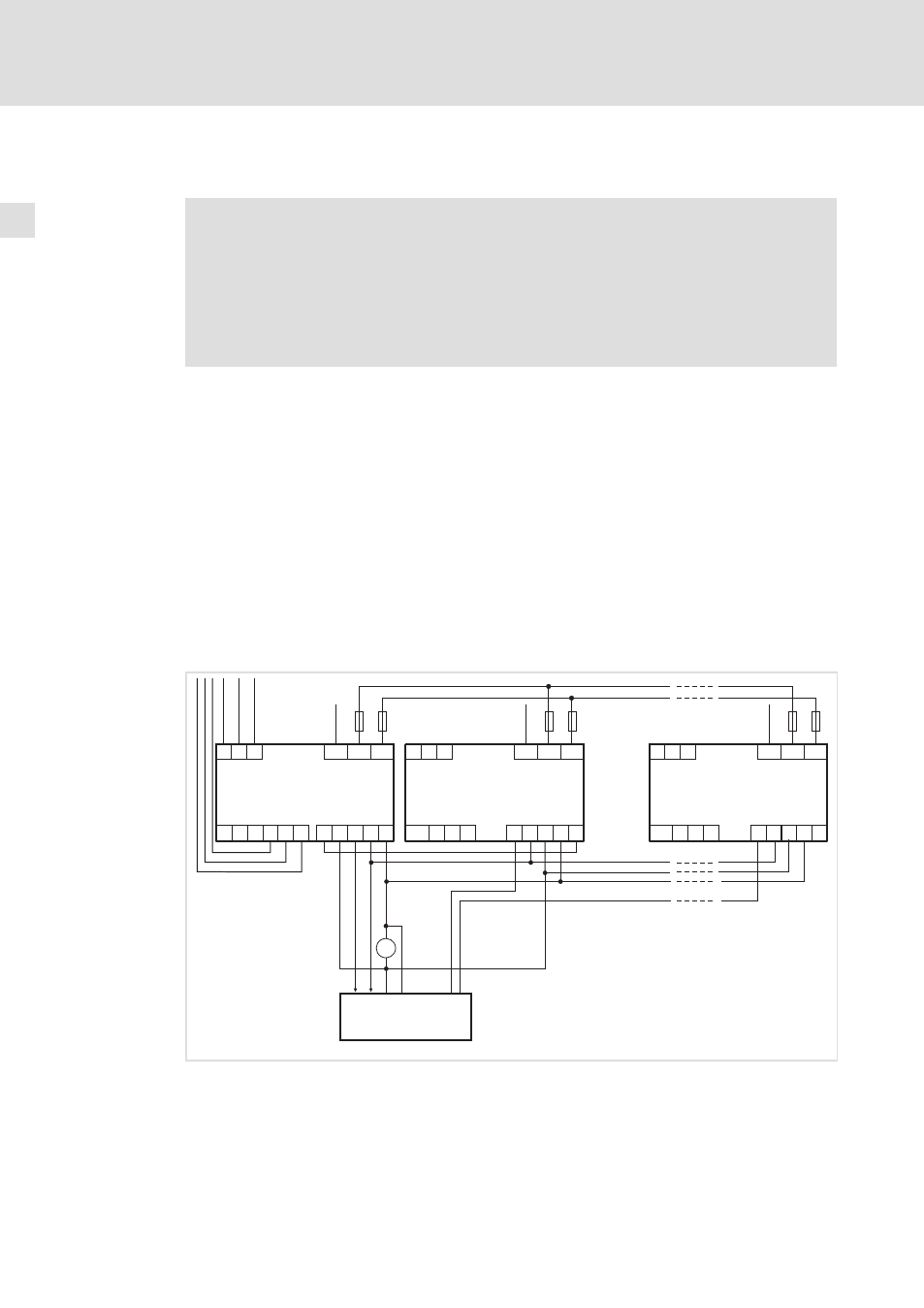
Uncontrolled shutdown of the drive system
The following illustration shows a possible solution in which the mains failure signal is
directly given to the controller. This means that in case of a mains failure the controllers are
inhibited independent of the operating status of the machine.
PE U V W
PE U V W
L1
L1
L1
L2
L2
L2
L3
L3
L3
24 V DC
39
Ex
Ex
28
28
Ax
59
39
Ax
59
E1 39 A1 A2 59
934x
Z2.1
Z4
Z2.n
PE
PE
PE
+UG
+UG
+UG
-UG
-UG
-UG
F4
F6
F8
F5
F7
F9
_
+
=
FAIL
L3’ L2’ L1’ L3.2L2.2L1.2
9340vrm008
Fig. 5−13
Circuit proposal − Uncontrolled shutdown of the drive system
934X
Regenerative power supply module
Z2.1 ... Z2.n
Controllers in the drive system
Z4
Higher−level control (PLC, PC)
F4...F9
DC−bus fuses