Landoll 3130 SERIES WING PACKER User Manual
Page 17
3-5
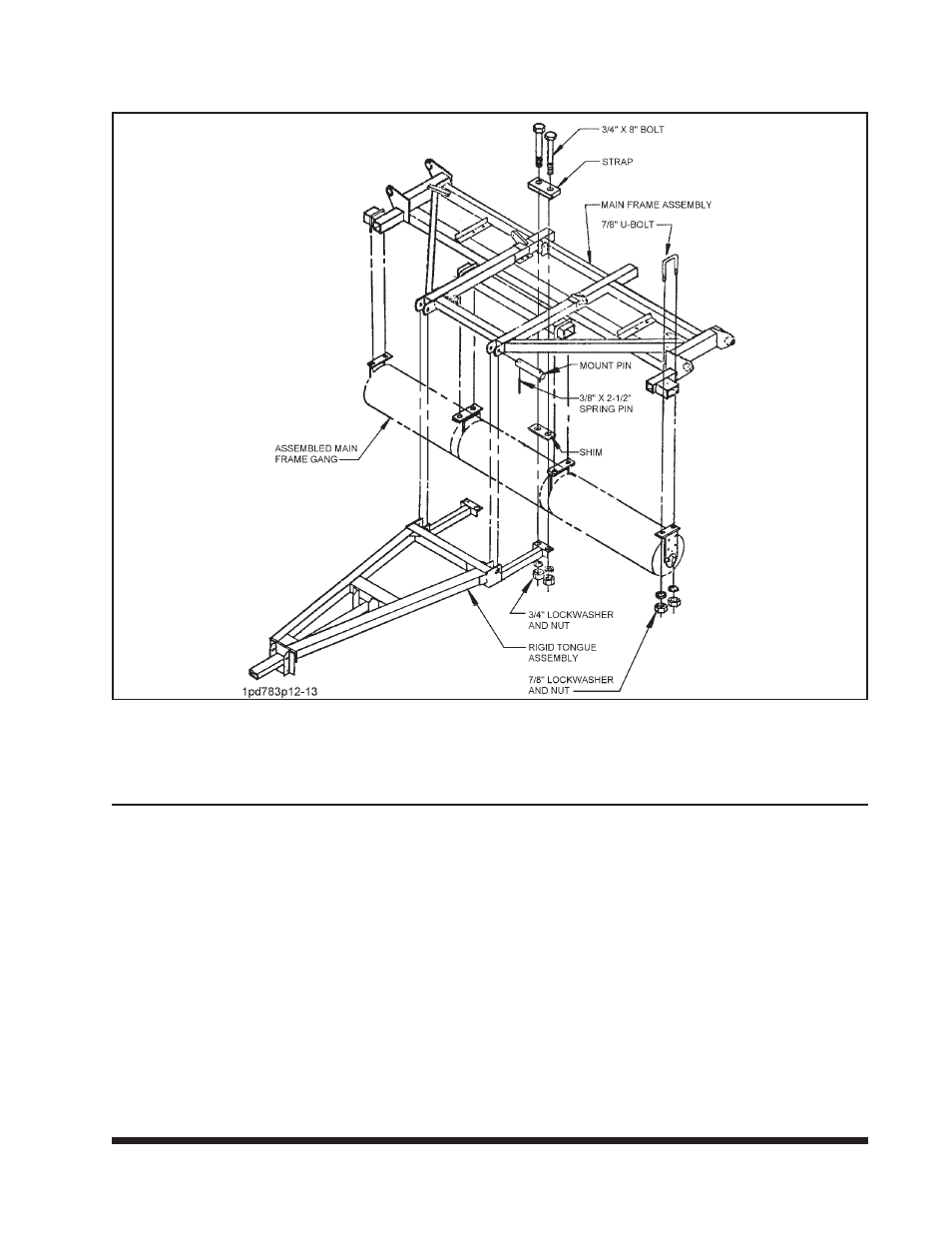
MAIN FRAME, ROLLER GANG, AND TONGUE ASSEMBLY -
27’, 31’, and 36’ MODELS
3-5.1
Gang Assembly
a. Slide rollers, spacers and bearing hangers
onto the axle. See Figures 3-18 through
3-23 for the type of roller and the size of
your machine. Notice that the diagrams on
these pages are viewing the packer from the
rear. It is important to install the bearing hang-
ers as shown. Be sure the grease fittings are
pointing to the rear. Be sure the rollers are
touching each other. Tighten lock collars.
3-5.2
Roller Gang To Main Frame
a. Raise the main frame off the floor.
b. Roll the main frame gang into position. Fas-
ten gang to the main frame with three 7/8" u-
bolts, lockwashers and nuts (See Figure 3-2).
c. Check to make sure that the bearing hang-
ers are perpendicular to the 4" x 6" tube.
When properly installed, there should be no
end thrust or side load on the bearings.
d. Tighten the 7/8" nuts to at least 200 ft.-lbs.
of torque.
3-5.3
Tongue To Main Frame
a. Assemble the tongue assembly to the main
frame using mount pins, 3/8” x 2-1/2” spring
pins, 3/4” x 8” bolts, straps, lockwashers, and
nuts.
b. By adding shims above or below the tube,
the tongue can be raised or lowered as de-
sired. This adjustment is described in Section
3-13, but must be done after the machine is
completely assembled.
3-5
Figure 3-3 Main Frame Gang Assembly - 27’, 31’, and 36’ Models