Figure 3-1: frame assembly - rigid models, Frame assembly - rigid models, Warning – Landoll 875 Series Tilloll User Manual
Page 18
3-2
F-60-0210 Edition
ASSEMBLY INSTRUCTIONS
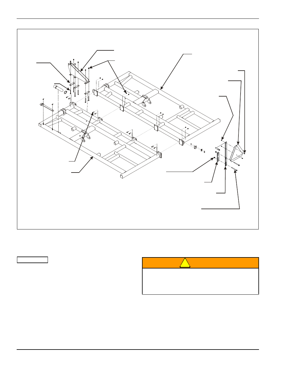
Figure 3-1: Frame Assembly - Rigid Models
Frame Assembly - Rigid Models
IMPORTANT
Read all safety precautions at the front of the section
before attempting any of the following procedures.
1.
Bolt frame halves together using 5/8-11 x 2 hex head
cap screws and hex lock nuts (See Figure 3-1.)
2.
Attach SMV mounting bracket and warning light bar
to rear frame near the center using 1/2-13 x 5-1/2
hex head cap screw and hex lock nuts.
3.
Attach SMV emblem to SMV mounting bracket using
1/4-20 x 1 hex head cap screws and hex lock nuts.
4.
Place frame assembly on stands approximately 36"
high.
5.
Install mast to frame using coulter support bars,
5/8-11 x 6 hex head cap screws, and hex lock nuts.
WARNING
MAST
5/8-11 HEX LOCK NUT
RIGHT HALF FRAME
1/4-20 X 1 HEX
HEAD CAP SCREW
SMV EMBLEM
1/4-20 HEX
LOCK NUT
1/2-13 HEX LOCK
NUT
WARNING LIGHT BAR
SMV MOUNTING BRACKET
1/2-13 X 5-1/2 HEX
HEAD CAP SCREW
COULTER
SUPPORT
BAR
5/8-11 X 6
HEX HEAD
CAP SCREW
5/8-11 X 2 HEX
HEAD CAP SCREW
LEFT HALF FRAME
545-106192-rig
Do not attempt to lift heavy parts (such as the
frame, disc gangs, rock shaft, and pull hitch)
manually. Use a hoist or a fork lift to move these
parts into position.