Bryant Deluxe 4 WAy Gas Furnase 355MAV User Manual
Page 9
a. Connect relief port tube (green label) to condensate trap.
b. Extend this tube (if required) by splicing to small diameter tube (factory-supplied in loose parts bag).
c. Determine appropriate length, cut, and connect tube.
E. Condensate Trap Field Drain Attachment
Refer to Condensate Drain section for recommendations and procedures.
F. Pressure Switch Tubing
The LOWER collector box pressure tube (pink label) is factory connected to the High Pressure Switch and should not require any modification.
NOTE: See Fig. 5 or 6 or tube routing label on main furnace door to check for proper connections.
G. Upper Collector Box and Inducer Housing (Unused) Drain Connections
1. Upper Collector Box Drain Connection
Attached to the UPPER collector box drain connection is a factory-installed corrugated, plugged tube (blue and white striped label). This
tube is plugged to prevent condensate leakage in this application. Ensure this tube is plugged.
NOTE: See Fig. 5 or 6 or tube routing label on main furnace door to check for proper connections.
2. Upper Inducer Housing Drain Connection
Attached to the UPPER (unused) inducer housing drain connection is a cap and clamp. This cap is used to prevent condensate leakage in
this application. Ensure this connection is capped.
NOTE: See Fig. 5 or 6 or tube routing label on main furnace door to check for proper connections.
H. Condensate Trap Freeze Protection
Refer to Condensate Drain Protection section for recommendations and procedures.
PROCEDURE 3—DOWNFLOW APPLICATIONS
A downflow furnace application is where furnace blower is located above combustion and controls section of furnace, and conditioned air is
discharged downwards.
A. Condensate Trap Location
The condensate trap must be removed from the factory-installed blower shelf location and relocated in selected application location as shown in
Fig. 2, 7, or 8.
To relocate condensate trap from the blower shelf to desired location, perform the following:
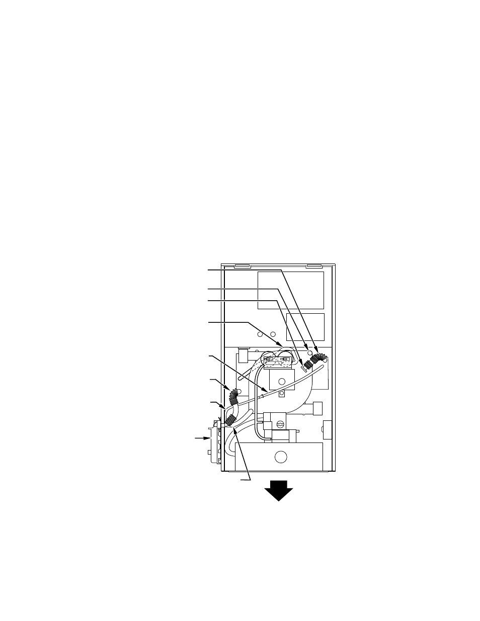
Fig. 7—Downflow Tube Configuration
(Left-Hand Trap Installation)
A94215
PLUG
COLLECTOR BOX
TUBE (GREEN)
COLLECTOR BOX
TUBE (PINK)
COLLECTOR BOX
DRAIN TUBE (BLUE
& WHITE STRIPED)
COLLECTOR BOX
EXTENSION TUBE
CONDENSATE
TRAP
INDUCER HOUSING
DRAIN TUBE (VIOLET)
CAP
COLLECTOR BOX
DRAIN TUBE (BLUE)
—9—