Bryant Deluxe 4 WAy Gas Furnase 355MAV User Manual
Page 50
2. Locate setup switches on control center. (See Fig. 31.)
3. See Table 11 for setup switch description. (See Fig. 30.)
4. Replace main furnace door and blower access panel.
NOTE: If a bypass humidifier is used, setup switch SW-3 (BPH) should be in ON position. This prevents nuisance limit trips caused by the
increased temperature in return air resulting from bypass.
NOTE: If modulating dampers are used, setup switch SW-5 (MZ) should be in ON position. This allows furnace control center to compensate
for modulating dampers. The control re-calibrates for new system static conditions once every minute while operating in low-heat or continuous
fan modes.
PROCEDURE 3—PRIME CONDENSATE TRAP WITH WATER
CAUTION: Condensate trap must be PRIMED or proper draining may not occur. The condensate trap has 2 internal
chambers which can ONLY be primed by pouring water into the inducer drain side of condensate trap.
1. Remove upper inducer housing drain connection cap. (See Fig. 54.)
2. Connect field-supplied 1/2-in. ID tube to upper inducer housing drain connection.
3. Insert field-supplied funnel into tube.
4. Pour 1 quart of water into funnel/tube. Water should run through inducer housing, overfill condensate trap, and flow into open field drain.
(See Fig. 55.)
5. Remove funnel and tube from inducer housing and replace drain connection cap and clamp.
PROCEDURE 4—PURGE GAS LINES
If not previously done, purge the lines after all connections have been made and check for leaks.
WARNING: Never purge a gas line into a combustion chamber. Never use matches, candles, flame, or other sources
of ignition for the purpose of checking leakage. Use a soap-and-water solution to check for leakage. Failure to follow this
warning could result in fire, explosion, personal injury, or death.
PROCEDURE 5—ADJUSTMENTS
A. Set Gas Input Rate
Furnace gas input rate on rating plate is for installations at altitudes up to 2000 ft.
In the U.S.A., the input rating for altitudes above 2000 ft must be reduced by 2 percent for each 1000 ft above sea level.
In Canada, the input rating must be derated by 5 percent for altitudes of 2000 ft to 4500 ft above sea level.
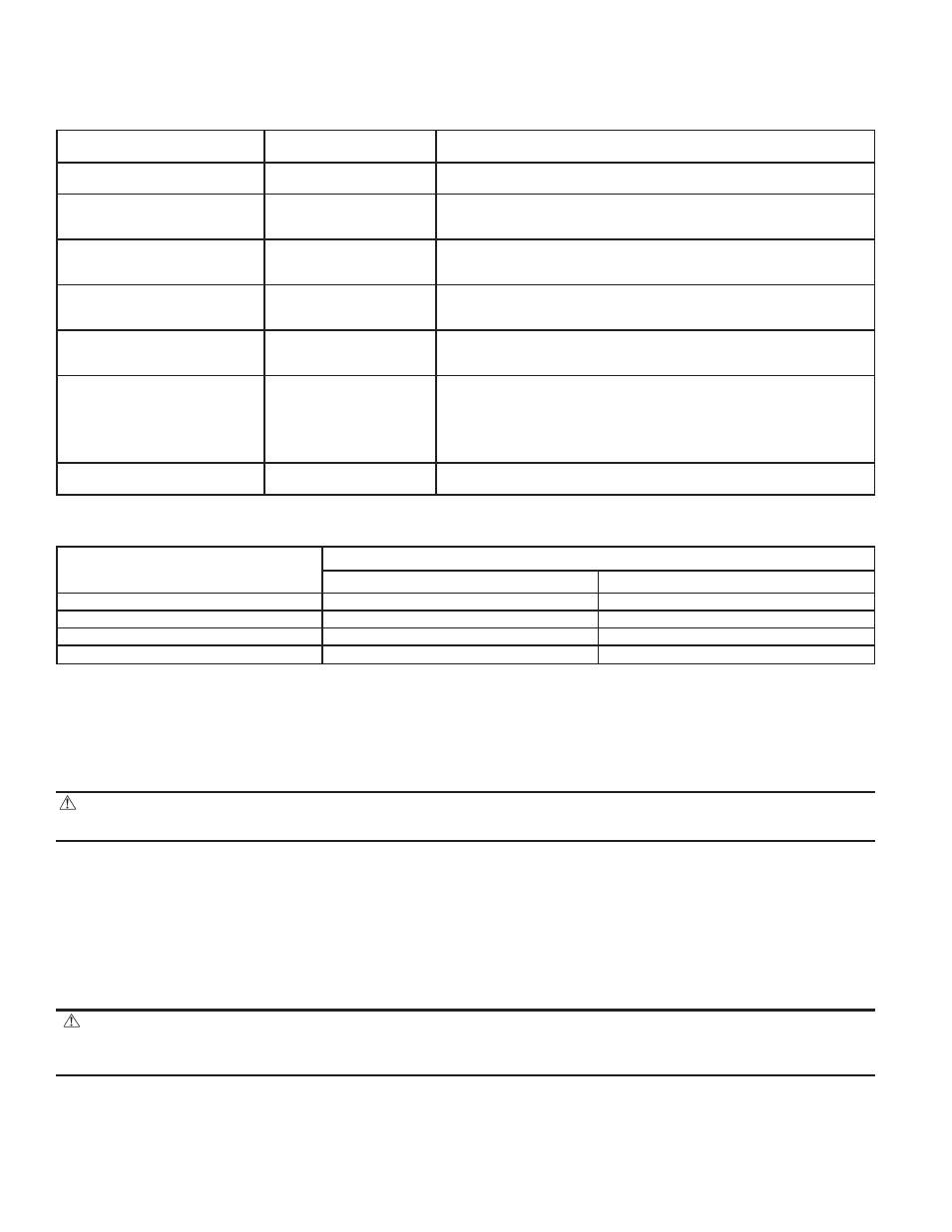
Table 11—Setup Switch Description
SETUP
SWITCH NO.
NORMAL
POSITION
DESCRIPTION
OF USE
SW-1
(FLT)
OFF
Turn switch to ON for fault history display. No thermostat signal
can be present for fault history display.
SW-2
(LOW)
OFF
Turn switch to ON to lock furnace in low-heat mode only or
when using a 2-stage thermostat with a R-W/W1 and R-W2 sig-
nals.
SW-3
(BPH)
OFF
Turn switch to ON when a bypass humidifier is used. This com-
pensates for higher return-air temperature and provides 15 per-
cent more airflow in low-heat mode only.
SW-4
(EMER HEAT)
OFF
Turn switch to ON to bypass microprocessor control. Furnace
will operate at high heat only with main blower and inducer mo-
tor operating at maximum RPM. NO safeties are bypassed.
SW-5
(MZ)
OFF
Turn switch to ON when modulating dampers are used. In this
mode, main blower speed is recalculated once every minute
while furnace is in low-heat or continuous fan mode.
SW-6
(COMP TEST)
OFF
Turn switch to ON to initiate component test. Furnace will oper-
ate inducer motor for 20 sec at low speed, operate inducer motor
for 20 sec at high speed, energize HSI for 15 sec, operate blower
for 20 sec at low speed, and operate blower for 20 sec at high
speed. SW-1 must be in OFF position. No thermostat signal can
be present for component test to be initiated.
SW-7 and SW-8
(Blower Off Delay)
See Table 12
Adjust switches to provide desired heating mode blower off de-
lay time. 90, 135, 180, or 225 sec.
Table 12—Blower Off Delay Setup Switch Position
DESIRED HEATING
MODE BLOWER
OFF DELAY (SEC)
SETUP SWITCH (SW-7 AND SW-8) POSITION
SW-7
SW-8
90
OFF
OFF
135
ON
OFF
180
OFF
ON
225
ON
ON
—50—