8 repair, 9 accessories, 10 troubleshooting – Festo DGP(L)-…-B User Manual
Page 8: 11 technical data
8
Repair
• Recommendation: Return the product to our repair service for overhaul.
This ensures that special attention will be paid to the necessary fine adjust-
ments and inspections.
• Information about spare parts and aids can be found at:
www.festo.com/spareparts
9
Accessories
Please select the appropriate accessories from our catalogue
www.festo.com/catalogue/DGP
10
Troubleshooting
Malfunction
Possible cause
Remedy
Uneven movement of the slide
One-way flow control valve not
fitted correctly
If possible reduce the exhaust
(not the supply air)
Guide rail not greased
Lubricate guide rail
7 Maintenance and care
Faults in position scanning
Ferritic parts in the vicinity of
the proximity sensor
Use parts consisting of
non-magnetic materials or
observe minimum clearances
5.3 Fitting electric
components
Heavy leakage
Cylinder is distorted
Fasten the cylinder to a flat
base.
Seal worn
Replace worn parts:
– yourself with wearing parts
kit
– by returning to Festo for
repairs
Sealing band pressed/sucked
in
Avoid creating a vacuum in the
piston chamber (e.g. only move
the unpressurised slide slowly)
Cylinder does not reach the
desired speed
Air volume not sufficient
– Select tubing with larger
diameter
– Switch volume upstream
High friction or counteracting
force
Observe maximum limits
Fig. 18
11
Technical data
DGP(L)
18
25
32
40
50
63
80
Pneumatic connection
M5
G
Á
G
Á
G
¼
G
¼
G
Å
G½
Mode of operation
Double-acting
Mounting position
Any
(Recommendation for stroke lengths
> 2 000 mm and
horizontal installation: Install the DGP(L) with the
sealing band facing down)
Operating medium
Use as cylinder:
Compressed air as per ISO 8573-1:2010 [7:–:–]
Use as
positioning axis:
Compressed air as per ISO 8573-1:2010 [6:4:4]
Operating pressure
[bar]
2 … 8
1.5 … 8
Ambient temperature
[°C]
–10 … +60
Theoretical force at 6 bar
[N]
153
295
483
754
1 178
1 870
3 016
Speeds
DGPL
(min … max)
GF
[m/s]
0,05 … 1
KF
[m/s]
0.2 … 3
GA
[m/s]
–
0.2 … 3
–
–
Cushioning length
PPV
[mm]
16
18
20
30
30
30
85
Cushioning
PPV
Pneumatic cushioning, adjustable at both ends
Max. energy
Diagrams
Catalogue specifications
Materials
End cap/profile
Anodised aluminium
Cover strip
Steel
Driver
Anodised aluminium
Slide
Anodised aluminium
Guide rail
GF
Anodised aluminium
KF
Steel
Corrosion-resistant steel
Seals
Nitrile rubber, polyurethane
Fig. 19
Permitted force and torque loading
DGP
18
25
32
40
50
63
80
GK
Fymax
[N]
–
Fzmax
120
330
480
800
1 200
1 600
5 000
Mxmax
[Nm]
0.5
1
2
4
7
8
32
Mymax
11
20
40
60
120
120
750
Mzmax
1
3
5
8
15
24
140
GV
Fymax
[N]
–
Fzmax
120
330
480
800
1 200
1 600
–
Mxmax
[Nm]
1
2
4
8
14
16
–
Mymax
22
40
80
120
240
240
–
Mzmax
2
6
10
16
30
48
–
Formula for combined loadings:
0, 4 × Fz
Fzmax.
+ Mx
Mxmax.
+
My
Mymax.
+ 0, 2 × Mz
Mzmax.
≤ 1
Fz
Fzmax.
≤ 1
Mz
Mzmax.
≤ 1
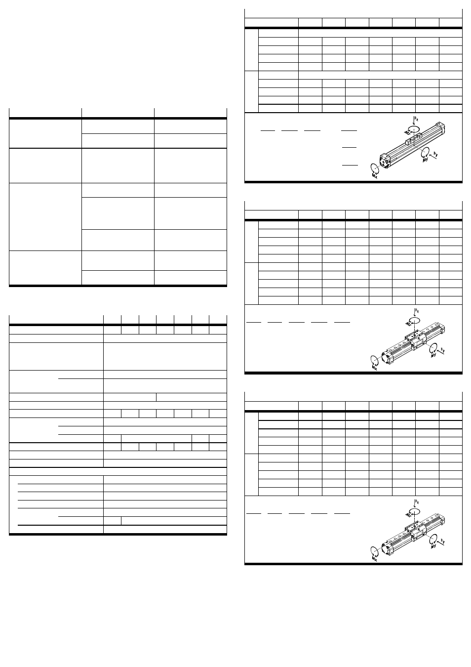
Fig. 20
Permitted force and torque loading
DGPL-GF
18
25
32
40
50
63
80
GK
Fymax
[N]
340
430
430
1 010
1 010
2 000
2 000
Fzmax
340
430
430
1 010
1 010
2 000
2 000
Mxmax
[Nm]
2.2
5.4
8.5
23
32
74
100
Mymax
10
14
18
34
52
140
230
Mzmax
10
14
18
34
52
140
230
GV
Fymax
[N]
330
400
395
930
870
1 780
–
Fzmax
330
400
395
930
870
1 780
–
Mxmax
[Nm]
2
5
8
21
28
66
–
Mymax
18
25
30
58
83
235
–
Mzmax
18
25
30
58
83
235
–
Formula for combined loadings:
Fy
Fymax.
+ Fz
Fzmax.
+ Mx
Mxmax.
+
My
Mymax.
+ Mz
Mzmax.
≤ 1
Fig. 21
Permitted force and torque loading
DGPL-KF
18
25
32
40
50
63
80
GK
Fymax
[N]
930
3 080
3 080
7 300
7 300
14 050
14 050
Fzmax
930
3 080
3 080
7 300
7 300
14 050
14 050
Mxmax
[Nm]
7
45
63
170
240
580
745
Mymax
23
85
127
330
460
910
1 545
Mzmax
23
85
127
330
460
910
1 545
GV
Fymax
[N]
930
3 080
3 080
7 300
7 300
14 050
–
Fzmax
930
3 080
3 080
7 300
7 300
14 050
–
Mxmax
[Nm]
7
45
63
170
240
580
–
Mymax
45
170
250
660
920
1 820
–
Mzmax
45
170
250
660
920
1 820
–
Formula for combined loadings:
Fy
Fymax.
+ Fz
Fzmax.
+ Mx
Mxmax.
+
My
Mymax.
+ Mz
Mzmax.
≤ 1
Fig. 22