3 installing the electric components, 6 commissioning, 1 commissioning the complete system – Festo DGP(L)-…-B User Manual
Page 7: 2 preparing for commissioning, 3 carrying out commissioning, 7 maintenance and care
5.3 Installing the electric components
If you are using proximity switches to scan positions:
• Make sure that the minimum distance L between static or moving ferritic masses
and the proximity switches corresponds to the values specified in the table
Fig. 11.
In this way you will avoid incorrect switching as a result of external influences.
Minimum distances L [mm]
DGP(L) 18
25
32
40
POS
L
40
4.2
4.8
5.6
DGP(L) 50
63
80
POS
L
11.4
14
5
Fig. 11 (POS = position of proximity switch)
• Use slot covers to prevent contamination in the sensor slots.
6
Commissioning
6.1 Commissioning the complete system
• Slowly pressurise the complete system. In this way you will prevent sudden
uncontrolled movements.
For slow start-up pressurization, use safety start-up valve type HEL.
6.2 Preparing for commissioning
In the case of heavy or medium effective loads or at high and medium slide
speeds:
• Use cushioning elements of sufficient size.
Without external cushioning devices the DGP(L) will withstand maximum speeds
and effective loads as per catalogue specifications.
Warning
Without external cushioning devices the DGP(L) may be damaged if the limit
values specified in the catalogue are exceeded.
• Even in the event of faults, the limit values must not be exceeded.
Before each commissioning procedure and in operation:
Warning
Fig. 12
Make sure that, in the positioning range,
– nobody can place his/her hand in the path of the
moveable mass (e. g. by providing a protective
grill).
– there are no foreign objects.
It should not be possible to touch the DGP(L)
until the mass has come to a complete standstill.
6.3 Carrying out commissioning
Commissioning the DGP(L) as a servopneumatic positioning axis:
Note
• Complete commissioning in accordance with the specifications for your
positioning system.
Commissioning the DGP(L) as a cylinder:
1. Close the one-way flow control valves
– for both sides at first completely,
– then open one rotation.
Fig. 13
Using the internal end position cushioning:
2. Close the adjusting screws for the internal end
position cushioning
– on both sides at first completely,
– then open one rotation.
Fig. 14
3. Pressurize the DGP(L) as follows:
– at first on both sides simultaneously. The slide will then move slightly to a
centre of equilibrium.
– Then exhaust the DGP(L) on one side. In this way you can avoid peak loadings
on the DGP(L) and in the compressed air network.
4. Start a test run.
5. Check whether the speed of the slide has to be modified.
For mass geometries with projection:
Warning
Fig. 15
Risk of collision!
• Note that the adjusting screws of the DGP(L)
may only be turned when the slide is at a stand-
still.
6. Open up the one-way flow control valves slowly until the desired slide speed is
reached.
7. Open the adjusting screws for the internal end position cushioning.
The slide should reach the end position without striking hard against it or
bouncing back.
7
Maintenance and care
Maintaining the band system:
• Clean the band system if required with a soft cloth.
Cleaning agents: all non-abrasive cleaning agents.
• Lubricate the surface of the band system if it no longer has a layer of grease.
Grease type: LUB-KC1.
Lubricating guide type
KF:
1. Make sure that the lubrication intervals in accordance with Fig. 16 are observed.
Lubrication intervals and types
First interval
5 000 km
Subsequent interval with special grease LUB-KC1 (silicone-free)
400 km
or: Subsequent interval with special grease LUB-RN2 (silicone-free)
5 000 km
Fig. 16
Note
The lubrication interval depends on the product load.
• Halve the lubricating interval (
Fig. 16) if one of the following situations
arises:
– dusty and contaminated environment
– Nominal stroke
> 2 m/s
– Ambient temperature
> 40 °C
– If the product has been in operation for
> 3 years.
If several situations are present at the same time, the lubrication interval is to be
divided into quarters.
2. Exhaust the DGPL.
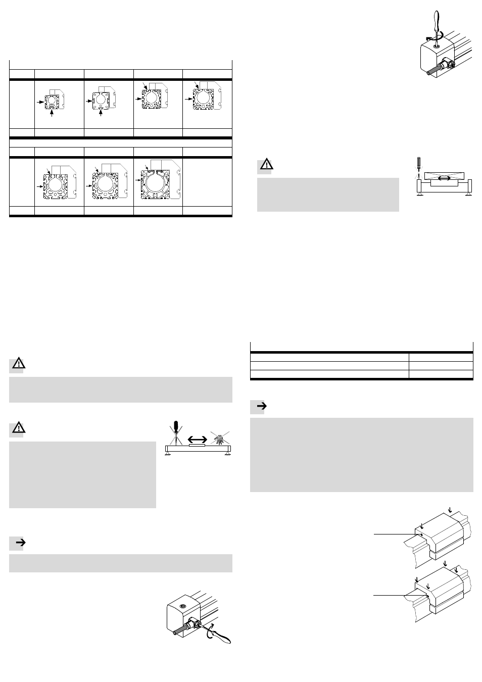
3. Lubricate the roller bearings via the
holes
aJ.
For this purpose use a grease gun
with pinpoint nozzle or alternatively a
disposable syringe with needle.
• Push the slide backwards and
forwards during lubrication.
Otherwise the grease cavities will
not be filled to an equal extent.
Fig. 17
DGPL-18-KF
DGPL-...-KF
aJ
aJ
4. Lubricate the surface of the band system if it no longer has a layer of grease
(grease type
Fig. 16).
Alternatively, Festo offers a service inspection which includes lubrication.
Otherwise the DGP(L) does not require any maintenance.