2 fitting pneumatic components – Festo DGP(L)-…-B User Manual
Page 6
2
1
3
4
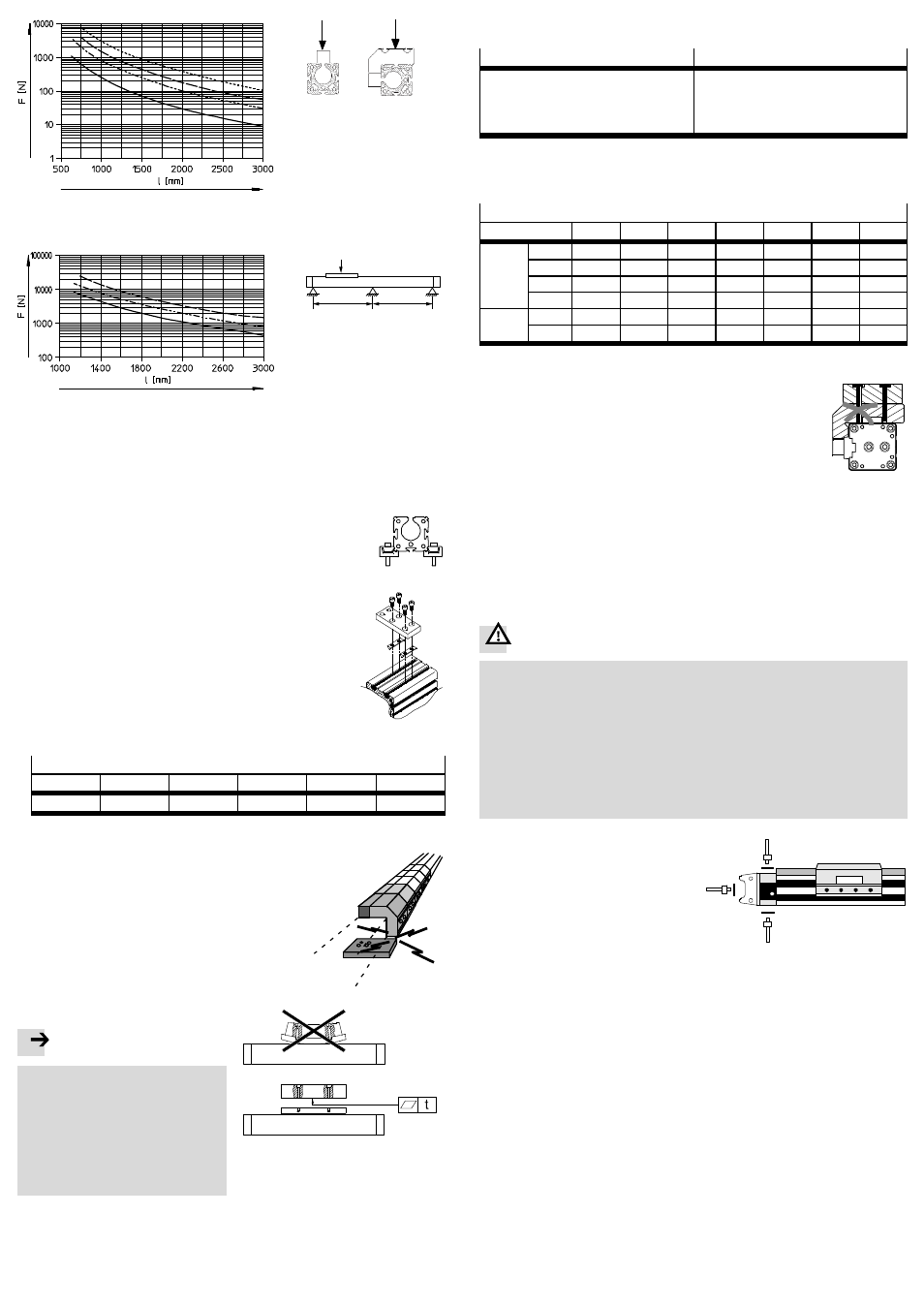
F
F
1 DGP…-18
2 DGP…-25
3 DGP…-32
4 DGP…-40
2
1
3
F
l
l
1 DGP…-50
2 DGP…-63
3 DGP…-80
Fig. 2: Necessary gaps between supports
Fitting central supports MUP:
1. Place the profile fastenings equally over the entire
length of the drive, and not just over the stroke
length.
2. Place the DGP(L) so that all the operating parts are
accessible.
DGP(L)-18 … 25
3. Place the central support on the DGP(L) in
accordance with Fig. 3.
When the slot nuts (size 32 … 80) are tilted, they
slide into the groove at each point on the profile.
DGP(L)-32 … 80
Fig. 3
4. Tighten the clamping screws evenly.
Tightening torques [Nm]
MUP-18/25 MUP-32
MUP-40
MUP-50
MUP-63
MUP-80
3
4.5
5.5
18
18
18
Fig. 4
5. Make sure the central support does
not collide with
the slide or the effective load (especially with
lateral attachment). In order to do this, push the
slide with the effective load once over the entire
positioning path.
Fig. 5
With hard and stiff effective loads:
Fig. 6
Note
If the slide is bent due to a buckled
effective load, it will reduce the service
life of the guide.
• Make sure the mounting surface of
the effective load exhibits the
following evenness (t):
– GF: t
≤ 0.03 mm
– KF: t
≤ 0.01 mm
To mount the effective load:
• Select a mounting option:
DGP
DGPL
1. Through holes and threaded holes in
the driver (
Fig. 1)
1. Slot nuts NSTL on the slide
2. Threaded holes and centring ele-
ments (
9 Accessories) on the
slide
Fig. 7
• When designing your screw connection for mounting the effective load, observe
the following maximum tightening torques:
Tightening torques [Nm]
DGP(L)
18
25
32
40
50
63
80
DGP
M5
3.5
3.5
3.5
–
–
–
–
M6
–
–
–
6
–
–
–
M8
–
–
–
–
12
12
–
M12
–
–
–
–
–
–
30
DGPL
M5
4.5
4.5
4.5
5
–
–
–
M8
–
–
–
–
15
15
15
Fig. 8
• If the mounting option with DGPL is used, the
screws must be shorter than the threaded hole.
Fig. 9
Effective loads with their own guide:
• Adjust the guides of the effective load and the DGP(L) so that they are exactly
parallel.
Only in this way can you avoid overloading on the slide
11Technical data:
permitted forces.
5.2 Fitting pneumatic components
For installation in a vertical or sloping position:
Warning
If there is a power failure, the work mass will slide down. Danger of crushing!
• Read the manuals for the positioning controller used (e.g. SPC11/SPC200).
There you will find pneumatic circuit diagrams with which the moving mass
can be prevented from sliding down (only with servopneumatic positioning).
• Check whether non-return valves HGL are required here (only if used as a
cylinder). In this way, you can prevent the work mass from sliding down sud-
denly.
• Check whether safety measures are necessary to prevent the mass from sink-
ing down slowly as a result of leakage (e.g. toothed latches or moveable
bolts).
• Select the compressed air ports.
In addition to the compressed air
ports provided at the factory (A),
there are also the alternative ports
(B, C). These are fitted with plug
screws.
A
= Compressed air ports
provided at the factory
B, C = Alternative ports
With variant …
-D2 (with bilateral air
ports) the air cannot be supplied on
one side only.
Fig. 10
A
C
B
Setting the speed (cylinder only):
• Only use one-way flow control valves of type GRLA.
For stroke lengths
> 500 mm:
If the DGP(L) is controlled by the SPC11 or SPC200, the compressed air must be
provided on both sides (variant …
-D2).
Only bilateral air supply will guarantee optimum dynamics.