Det-Tronics U9500 Infiniti Gas Transmitter User Manual
Page 8
95-8444
6
10.1
7. Fasten the transmitter module to the mounting
bracket with the two captive screws located inside
the notch on either side of the top of the transmitter.
Remove the wire clip and set it aside.
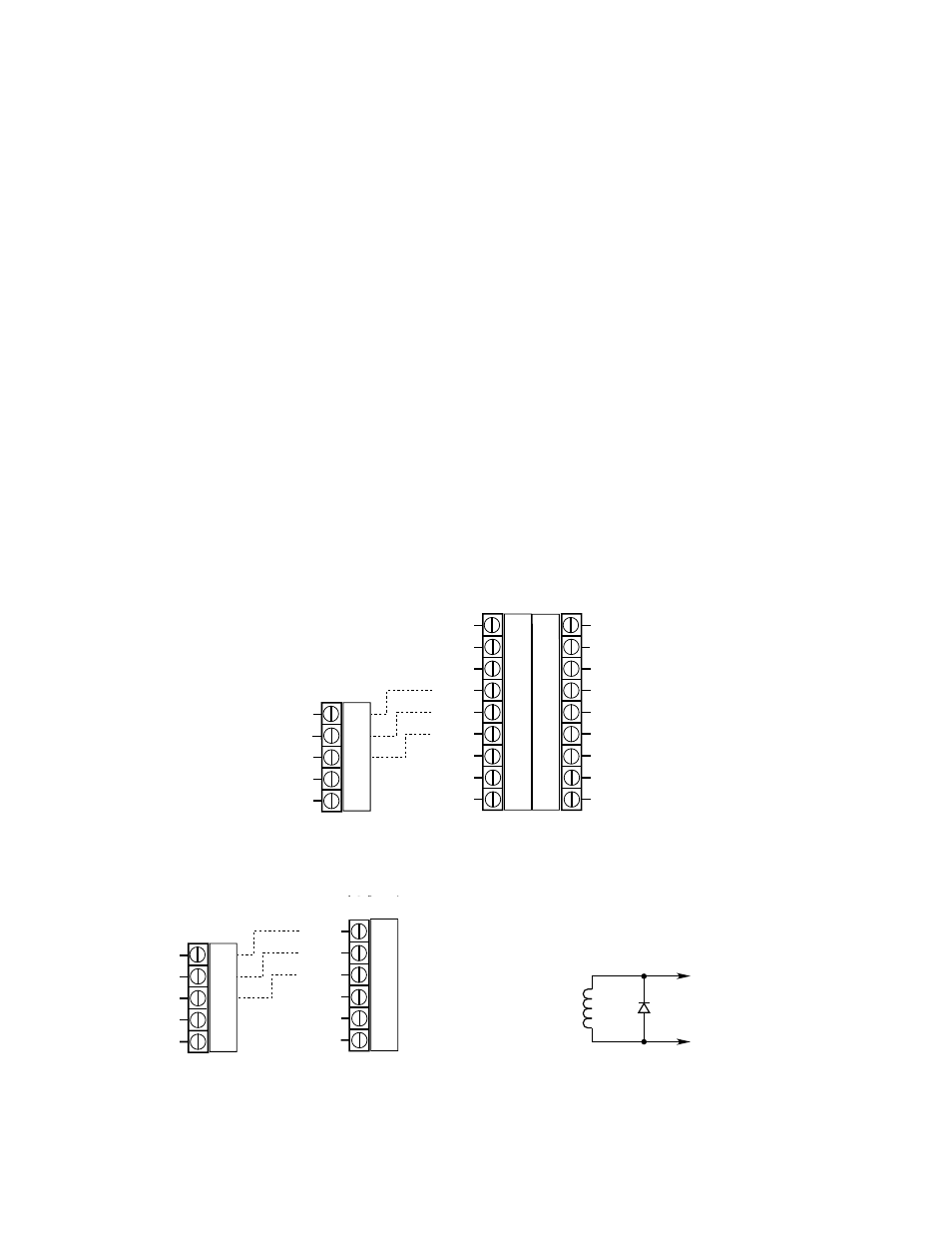
8. See Figures 4 and 5 for field wiring terminal
designation.
9. Connect the power and current output leadwires to
the screw terminals on the plug that is provided. See
Figures 7, 8, 9 and 10 for examples of transmitter
wiring. Connect the shield to earth ground at the
power supply. The panel or field end of the shield
should not be grounded at the transmitter. Contact
the factory for further assistance.
10. For Relay models, refer to Figures 7 and 8 when
connecting external loads to the relay outputs. For
models without relays, proceed to step 11.
iMPOrTanT
Direct connection of 120/240 vac to the relay
terminals inside the transmitter enclosure is
not permitted, since switching relay contacts
can induce electrical noise into the electronic
circuitry, possibly resulting in a false alarm or other
system malfunction. If the application requires
that ac powered equipment be controlled by the
transmitter, the use of externally located relays is
required.
External relays, solenoids, motors, or other devices
that can cause inductive transients should be transient
suppressed. Place a diode across the coil for dc devices.
See Figure 6.
11. An external reset switch can be wired as shown in
Figures 7, 8, 9 and 10. The use of shielded wire is
recommended for wiring the switch.
12. Check all field wiring to ensure that the proper
connections have been made. Refer to local codes
to be sure wiring and conduit seals are installed
properly.
Warning
When in non-latching mode, the control device
must latch the alarm output.
CaUTiOn
Wires can become pinched between the cover
and base if they are not properly tucked down
inside the enclosure. The wire clip will prevent this
problem when installed correctly.
13. Replace the wire clip and place the cover back on
the transmitter enclosure.
AUX RELAY LOW RELAY HIGH RELAY
NC COM NO NC COM NO NC COM NO
FLT RELAY
S
POWER
RESET
PW
IN
NO COM NC
–
+
CAL
HIGH ALARM RELAY
NORMALLY OPEN CONTACT
HIGH ALARM RELAY
COMMON CONTACT
HIGH ALARM RELAY
NORMALLY CLOSED CONTACT
LOW ALARM RELAY
NORMALLY OPEN CONTACT
LOW ALARM RELAY
COMMON CONTACT
LOW ALARM RELAY
NORMALLY CLOSED CONTACT
AUXILIARY ALARM RELAY
NORMALLY OPEN CONTACT
AUXILIARY ALARM RELAY
COMMON CONTACT
AUXILIARY ALARM RELAY
NORMALLY CLOSED CONTACT
FAULT RELAY
NORMALLY OPEN CONTACT
FAULT RELAY
COMMON CONTACT
FAULT RELAY
NORMALLY CLOSED CONTACT
*
SPARE
POWER
COMMON
POWER
24 VDC +
EXTERNAL
RESET
POINTWATCH
CALIBRATE
4 TO 20 MILLIAMPERE
INPUT SIGNAL
S
POWER OUT
–
+
+
–
*
SPARE
POWER
COMMON
POWER
24 VDC +
+ 4 TO 20 MILLIAMPERE
OUTPUT SIGNAL
– 4 TO 20 MILLIAMPERE
OUTPUT SIGNAL
*
THE SPARE TERMINALS ARE CONNECTED TOGETHER INTERNALLY
AND ARE NOT CONNECTED TO ANY OTHER TERMINALS INTERNALLY
B1904
**
**
THESE TERMINALS ARE CONNECTED INTERNALLY
**
Figure 4—Field Wiring Terminals, Transmitter with Relays
FLT RELAY
S
POWER
RESET
PW
IN
NO COM NC
–
+
CAL
*
SPARE
POWER
COMMON
POWER
24 VDC +
EXTERNAL
RESET
POINTWATCH
CALIBRATE
4 TO 20 MILLIAMPERE
INPUT SIGNAL
S
POWER OUT
–
+
+
–
*
SPARE
POWER
COMMON
POWER
24 VDC +
+ 4 TO 20 MILLIAMPERE
OUTPUT SIGNAL
– 4 TO 20 MILLIAMPERE
OUTPUT SIGNAL
*
THE SPARE TERMINALS ARE CONNECTED TOGETHER INTERNALLY
AND ARE NOT CONNECTED TO ANY OTHER TERMINALS INTERNALLY
A1905
THESE TERMINALS ARE CONNECTED INTERNALLY
**
**
**
Figure 5—Field Wiring Terminals, Transmitter without Relays
RELAY
SOLENOIDS
MOTORS
INDUCTION DEVICES
1N4004
TYPICAL
B0179
POSITIVE
NEGATIVE
MOV
HOT
NEUTRAL
120 VOLT – V13OLA10A
220/240 VOLT – V275LA20A
GE
TYPICAL
{ }
+
–
DCV LOADS
A0179
Figure 6—Transient Suppression for Inductive Loads