Description – Det-Tronics U9500 Infiniti Gas Transmitter User Manual
Page 5
95-8444
3
10.1
DESCRIPTION
The U9500 is a single channel gas detection device. In
addition to the standard 4-20 mA analog signal output,
the U9500 offers 4 optional relay outputs for fault and
alarm indications. The 4 outputs are: fault, high alarm,
low alarm, and auxiliary alarm. The relays have form C
(SPDT) contacts. Low, auxiliary and high alarm relay
contacts are selectable as a group for latching or non-
latching operation. During normal operation, the fault
relay is non-latching, but for initialization faults, the fault
relay latches. The alarm relays are also selectable, as a
group, for normally energized or de-energized with no
alarms. The fault relay is always normally energized for
no fault.
NOTE
Since the relays can be programmed to be either
energized or de-energized on alarms, the term
“actuate” is used to indicate that the output is in an
alarm condition.
The U9500 provides an eight character, single line, alpha-
numeric LCD display. The U9500 has four switches
located on the display. The visible three switches are
single pole, normally open push buttons, and are
designated as: Setup\accept, increase, and decrease.
The fourth switch is a magnetic reed switch, designated
cal/reset, which is used by the customer for non-intrusive
calibrations and for resetting of the U9500.
Two additional options are available for resetting the
transmitter. A user supplied switch can be wired to the
transmitter terminal block and used to reset the device
from a remote location.
In addition, Detector Electronics offers a special optional
enclosure with a pushbutton pre-installed within a multi-
port electrical enclosure for customers who do not prefer
magnetic switches.
The U9500 is compatible with the entire Detector
Electronics sensor family. In some cases, special
personality cards are required to ensure proper
operation with a specific sensor, including the Det-
Tronics Combustible Gas sensors. The proper U9500
model must be ordered by the customer to ensure
proper operation and markings for the desired sensor
type. Refer to Appendix C for combustible gas sensor
ATEX/CE ratings and installation details. Refer to form
90-1041 for specification details.
Modes of operation
The U9500 has three main operating modes:
–
Normal
–
Calibrate
–
Setup (also called Configuration).
Normal mode is the default mode, no buttons pushed.
Three minor modes also exist:
–
Setpoint display
–
Reset
–
Power up.
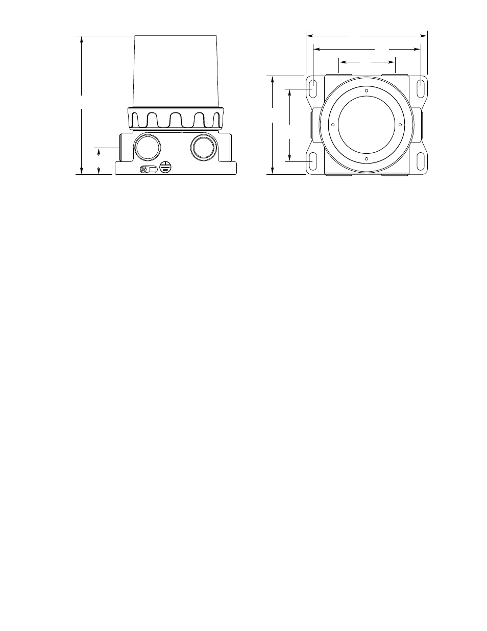
3.46
(8.8)
NOTE: TO MOUNT THE TRANSMITTER, DRILL 5/6" (7.9375mm) HOLES
AND USE 1/4" (6.35mm) BOLTS.
4.7
(11.9)
2.7
(6.9)
5.2
(13.2)
5.86
(14.9)
6.57
(16.7)
1.28
(3.3)
B2307
Figure 1—Infiniti Transmitter Dimensions in Inches (Centimeters)