Appendix f – modbus communication, Appendix f – Det-Tronics PIRECL Infrared Carbon Dioxide Gas Detector PointWatch Eclipse User Manual
Page 42
f-1
95-8676
2.1
AppenDix f
MoDbUS CoMMUnICaTIon
oVerVIeW
This appendix outlines the communication protocol and related memory structures that define the interface between
PointWatch Eclipse Gas Detector and a system MODBUS Master. The system MODBUS Master is defined as any
device capable of reading and writing to the holding register area of a MODBUS slave device. This includes proprietary
software, HMI systems such as Wonderware and The FIX, PLCs and DCSs.
The Eclipse will respond as a slave device to a MODBUS Master, allowing the master to control data flow. A MODBUS
memory map is defined, which divides memory into functional blocks consisting of: factory constants, configuration
information, real time status, control and device defined information. Each block is then subdivided into individual
variables that may be simple integers or floating point numbers.
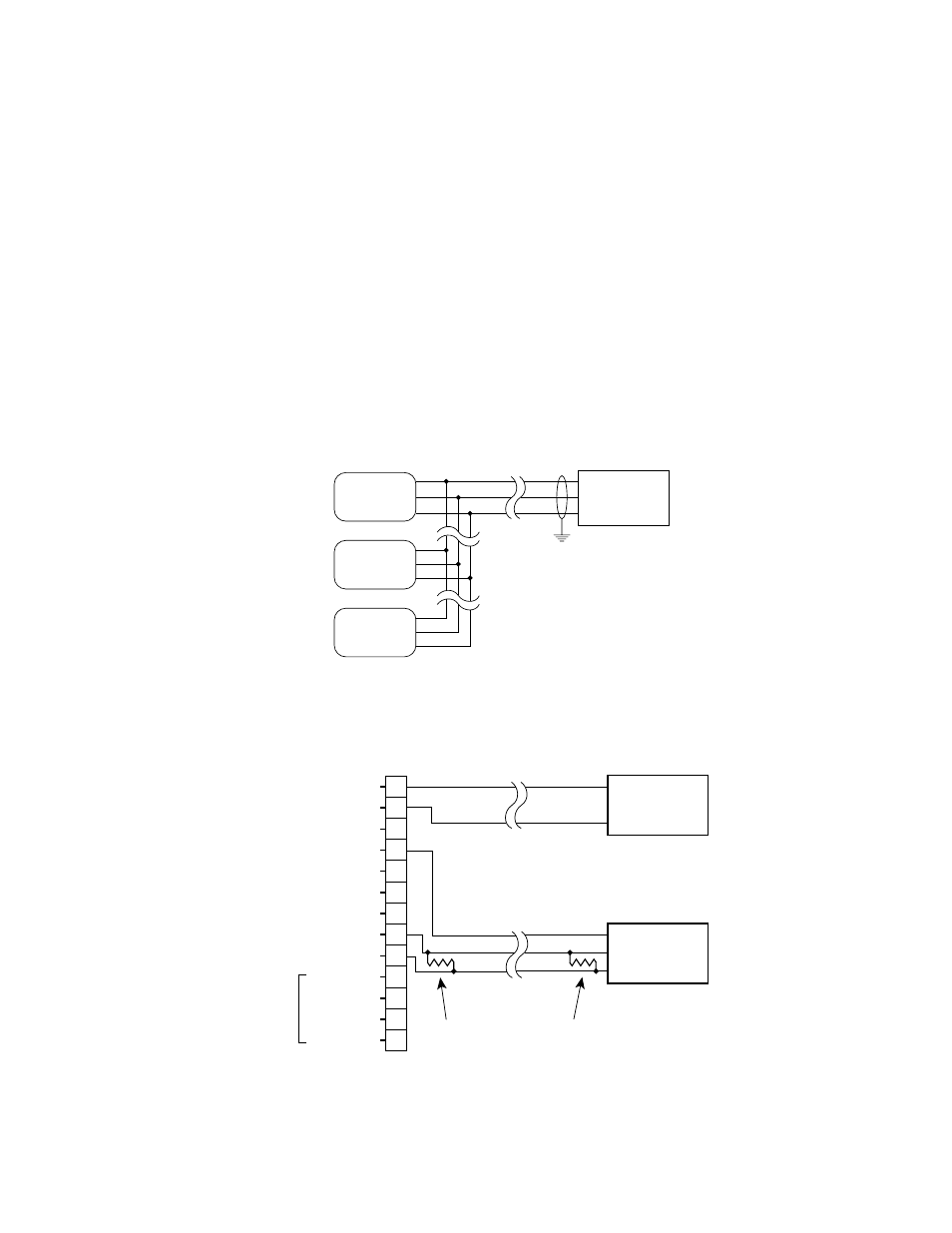
WIrInG
Typical RS-485/Modbus communication architecture is indicated in the diagram below. Eclipse units act as slave
devices to a Modbus Master. Multiple Eclipse units are daisy-chained for RS-485 communication. If long cable runs
are used, 120 Ohm end-of-line termination resistors may be required.
Individual Eclipse units are wired as shown below. Note the inclusion of the end-of-line termination resistor.
For more information, refer to the EIA RS-485-A standard.
A2340
MODBUS
MASTER
GND
A
B
ECLIPSE
SLAVE #1
ECLIPSE
SLAVE #2
ECLIPSE
SLAVE #N
A2341
–24 VDC
–24 VDC
+24 VDC
+24 VDC
CALIBRATE
+ 4-20 MA
– 4-20 MA
RS-485 A
RS-485 B
RELAY POWER
FAULT
LOW ALARM
HIGH ALARM
NO USER CONNECTION
1
2
3
4
5
6
7
8
9
10
11
12
13
24 VDC
POWER SUPPLY
+
–
MODBUS
MASTER
GND
A
B
PIRECL
120 OHM TERMINATION RESISTOR
ON MASTER AND LAST SLAVE IN DAISY CHAIN