Caution – COATS 7xxx Series Tire Changer User Manual
Page 9
Important: Always read and follow operating instructions.
• 5
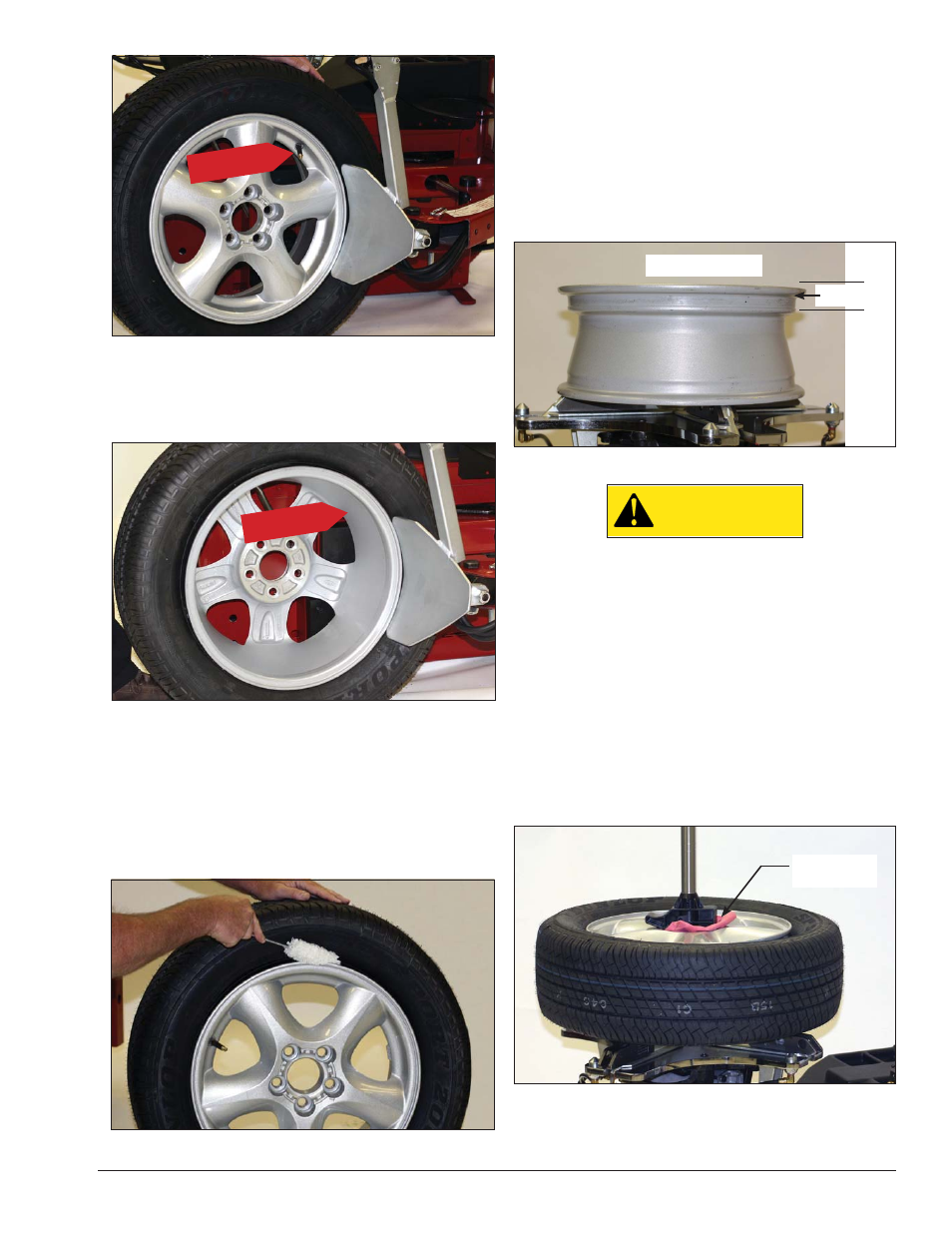
Figure 3 - Position Tire and Bead Loosener Shoe with Valve
Stem in 2 o’clock Position.
3.
Turn the wheel around and repeat loosening pro-
cedure on the other side of the wheel (figure 4). This
should be the long side of the drop center (figure 2).
Figure 4 - Position Tire and Bead Loosener Shoe With Wheel
Turned Around and Valve Stem in 2 o’clock Position.
G. It will be easier to outside clamp the wheel to
the table top if the long side of the rim is loosened
last.
4.
Apply tire manufacturer’s approved rubber lubricant
liberally to entire circumference of both tire beads after
loosening (figure 5).
Figure 5 - Apply Rubber Lubricant to Tire Beads
5.
Determine the mounting side of the wheel. The
mounting side is the narrow side of the drop center. See
figure 2 for more information on the drop center.
Note: The wheel clamps can be positioned in one of
two different ranges: Use the inner holes for 6-22-inch
diameter wheels and the outer holes for 8-24-inch
wheels.
6.
Place tire/wheel assembly on table top with mount-
ing side up (figure 6).
Figure 6 - Place Tire/Wheel Assembly on Table top
CAUTION
Clamp control pedal must be in the full up
or full down position (detent position) to
maintain clamping force on wheel.
7.
Use Robo Arm to apply pressure to aid in clamping
rim (figure 7). Use the clamp control pedal to move the
clamps inward (push pedal down) or outward (lift pedal
up). Engage the detent position (pedal in full up or full
down position) to maintain clamped or unclamped
pedal position.
Clamp steel wheels from the inside (clamps push out-
ward against wheel). Clamp mag and custom wheels
from the outside (clamps push inward against the
outside rim edge). Refer to the Performance Tires and
Wheels section.
Figure 7 - Robo Arm Aids Clamping
Valve Stem at
2 o’clock Position
Narrow Side
Mounting Side Up
Protective Pad
or Cloth
Valve Stem at
2 o’clock Position