COATS 7xxx Series Tire Changer User Manual
Page 13
Important: Always read and follow operating instructions.
• 9
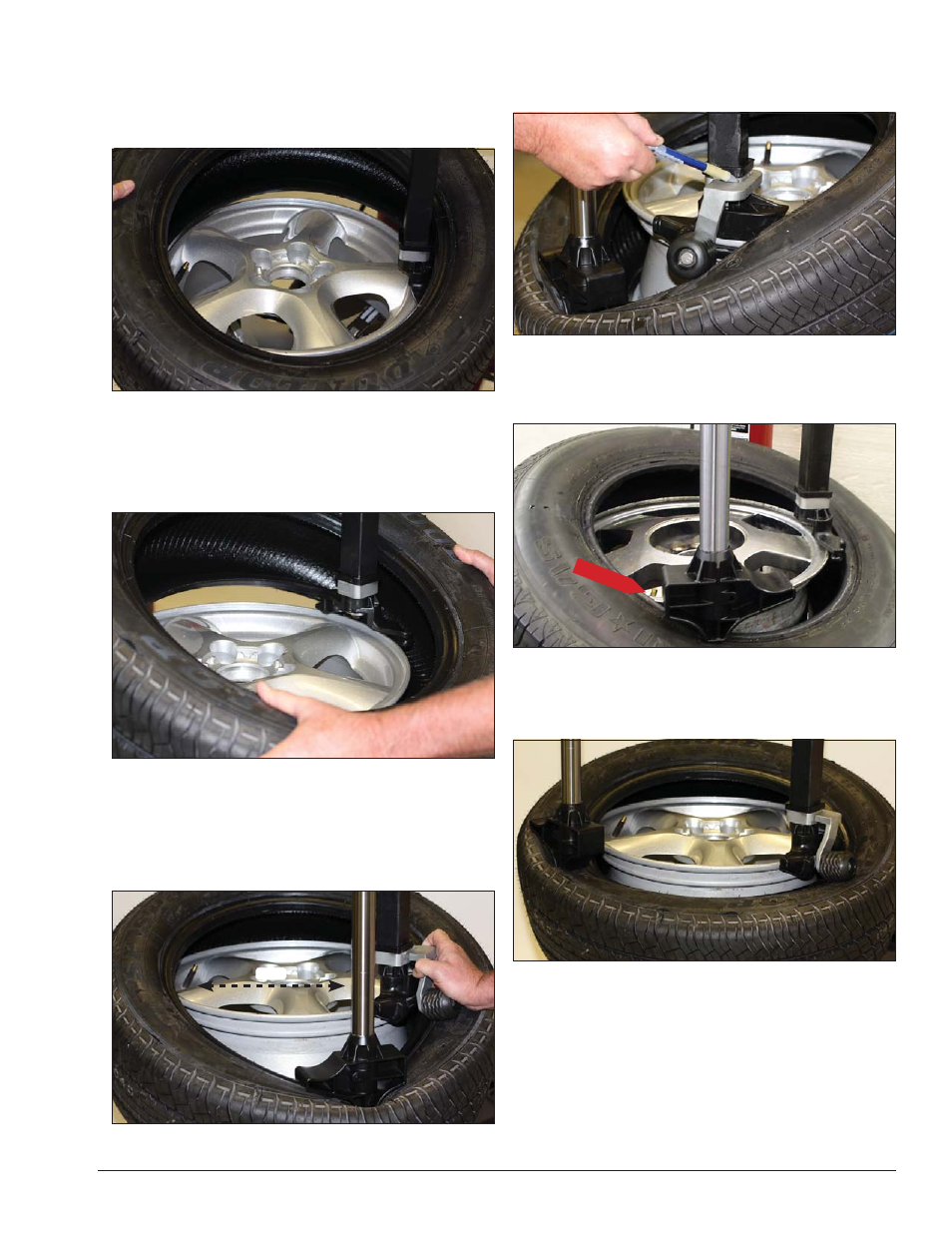
4.
Place tire over wheel and move swing arm into
position making sure the valve stem is at the 9 o’clock
position in front of bead lock. Position tire so that lower
bead is above the rear extension of the mount/demount
tool and below the front knob (figure 19).
Figure 19 - Position Tire Against Mount/Demount Tool
5.
Depress table top pedal and rotate wheel to mount
lower bead. Use drop center of wheel by pushing down
on tire just ahead of the mounting tool, and follow as
tire rotates (figure 20). Rotate table top until lower bead
is mounted.
Figure 20 - Mounting Lower Bead
6.
For top bead installation, rotate table top until
the valve stem on wheel is 180 degrees ahead of the
mount tool (3 o’clock position). Pull ring on locking pin
and attach Duckhead roller to the Duckhead mount tool;
using Robo Arm to assist (figure 21).
Figure 21 - Position Valve Stem 180º Ahead of Mount Tool
6a.
Release locking pin making sure the Duckhead
roller mount is fully engaged on the arm bracket; with
no gap (figure 20a).
Figure 20a - Duckhead Roller Properly Mounted On Bracket
7.
Use Robo Arm™ to push down on tire 90 degrees
clockwise from mount/demount tool to allow bead to
utilize drop center area of rim.
Fig 22 - Use Robo Arm To Hold Tire In Rim Drop Center
8.
Depress table top pedal and rotate tire until bead
is mounted. Be careful to ensure bead stays in the rim
drop center in the area ahead of Duckhead.
Figure 23 - Mounting Top Bead
N. If table top rotation stalls, reverse the table
top momentarily until tire bead is again loose on
the wheel. Reposition tire on Duckhead mount/
demount tool make sure bead is correctly posi-
tioned in drop center of the wheel; then attempt
mounting again.
180º
Valve Stem