Shaft seal and shaft replacement, Shaft seal and shaft replacement -63, Shaft seal removal -63 – JLG 450A_AJ Series II Service Manual User Manual
Page 303: Installation of shaft seal -63
SECTION 5 - HYDRAULICS
3121290
– JLG Lift –
5-63
5.
Install new O-ring on valve plug. Reinstall poppet,
spring, and plug (with shims and O-ring) into pump
housing. Torque to 40-100 ft-lb (55-135 Nm).
SCREW ADJUSTABLE STYLE
1.
Mark plug, lock nut, and housing to maintain original
adjustment before removing screw adjustable relief valve
plug. Loosen lock nut (1-1/16" Hex) and remove plug (8
mm Int. Hex). Remove O-ring from plug.
2.
Remove spring and poppet from housing.
3.
Inspect poppet and mating seat in housing for damage
or foreign material.
4.
Install new O-ring on valve plug. Reinstall poppet and
spring. Reinstall plug and lock nut. Torque to 34 - 42 ft-lb
(47-57 Nm), aligning marks made at disassembly.
5.
Check and adjust charge pressure if necessary. For screw
adjustable “anti-stall” charge relief valves, an approxi-
mate rule of thumb is 2.8 bar/quarter turn (40 psi/quar-
ter turn).
6.
Measure charge pressure (port M3) with pump in stroke.
Charge pressure should level off when relief setting is
reached.
Shaft Seal and Shaft Replacement
A lip type shaft seal is used in Series 42 pumps. Seal and shaft
can be replaced without major unit disassembly. Replacement
generally requires removing pump from machine.
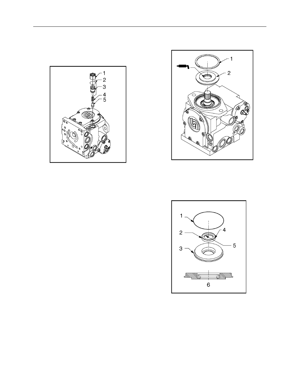
Figure 5-112. Installation of Shaft Seal
1. Lock Nut
2. O-Ring
3. Plug
4. Spring T-Seal
5. Poppet
Figure 5-110. Screw Adjustable Charge Relief Valve
Components
1. Retaining Ring
2. Seal Carrier Assembly
Figure 5-111. Shaft Seal Removal
1. O-Ring
2. Seal
3. Seal Carrier
4. Use sealant on outside diameter
5. Inside Lip (face down)
6. Press Seal to Bottom of Seal Carrier