Section layout, Section layout -108 – JLG 450A_AJ Series II Service Manual User Manual
Page 148
SECTION 3 - CHASSIS & TURNTABLE
3-108
– JLG Lift –
3121290
3.17 DGC DIAGNOSTIC SUPPORT AND TROUBLE CODE
DEFINITIONS
This section defines diagnostics and recommended trouble-
shooting procedures associated with EControls, Diesel Gover-
nor Control (DGC), and Engine Control Module (ECM) used on
industrial engines.
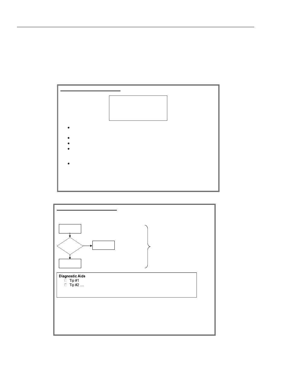
Section Layout
This section is organized in the following manner:
DTC XXXX- Diagnostic Condition
Block Diagram of Circuit
External Hardware Input/Output- This identifies the hardware that either sends an input
to the ECM or is driven by and ECM output.
Check Condition- This defines what condition to troubleshoot the fault condition.
Fault Condition(s)- This identifies the condition(s) that set the fault.
Corrective Action(s)- This identifies the RECOMMENED corrective action(s) that the
ECM is generally programmed to perform. In some instances, the calibration
engineer(s) may choose to perform a different action.
Emissions or Non-emissions related fault
Text to identify the circuit of interest and its use for control.
Text to describe t he conditions that cause the fault to set.
DTC XXXX- Diagnostic Condition
Note: Helpful tips used to aid troubleshooting
Yes
No
Troubleshooting flow
chart