Hydraulic pump bolt torque chart -58 – JLG 450A_AJ Series II Service Manual User Manual
Page 298
SECTION 5 - HYDRAULICS
5-58
– JLG Lift –
3121290
13.
Gently slide gear housing over rear bearing block
assembly. Slide housing down until it engages dowel
pins. Press firmly in place with hands, do not force or use
any tool. Check intake port in housing is on same side as
open end of E-seal, and marked lines on mounting
flange and gear housing are aligned.
NOTE:
Rear bearing block surface should be slightly below gear
housing face. If bearing block is higher than rear face of
gear housing, E-seal or O-ring have shifted out of groove.
Remove gear housing and check seal installation.
14.
Install two remaining dowel pins in rear of gear housing,
if applicable. Place end cover over back of pump.
15.
Install four spacers (if applicable) and hex head bolts
through bolt holes in end cover. Hand tighten.
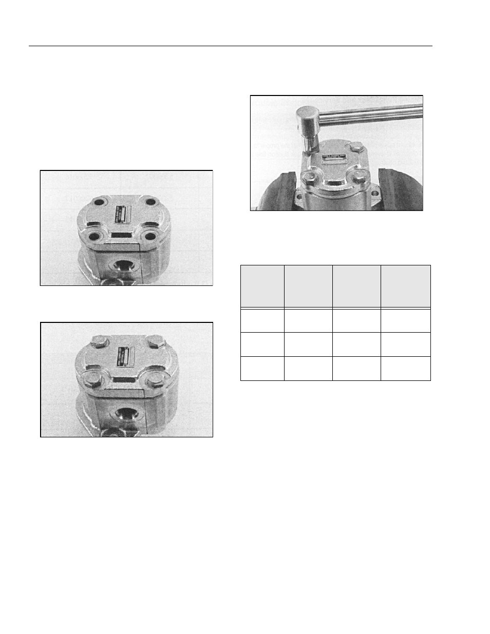
16.
Place mounting flange of pump in protected jawed vise.
Torque bolts alternately to torque chart specifications.
All torque figures are for ”dry torque” bolts.
17.
Remove pump from vise.
18.
Place a small amount of clean oil in pump inlet and
rotate drive shaft away from inlet one revolution. If drive
shaft binds, disassemble pump and check for assembly
problems. Reassemble pump.
Table 5-1.Hydraulic Pump Bolt Torque Chart
Pump
Series
Thread Size
Torque
Values,
Black Oxide
End Cover
Torque
Values, Zinc
Plated End
Cover
W-600
M 8 x 1.25
18-21 ft-lb
24-30 Nm
16-18 ft-lb
21.7-24.4 Nm
W-900
M 10 x 1.5
50-55 ft-lb
68-75 Nm
38-43 ft-lb
51.5-58.3 Nm
W-1500
M 12 x 1.75
80-85 ft-lb
108-115 Nm
68-73 ft-lb
92.2-99 Nm