8 air cleaner assembly, 1 air cleaner assembly removal, 2 air cleaner assembly installation – JLG 4013PS Service Manual User Manual
Page 105: 9 engine replacement, 1 engine removal, Air cleaner assembly, Engine replacement, Air cleaner assembly removal, Air cleaner assembly installation, Engine removal
7-9
3508PS, 3509PS, 3512PS, 3513PS, 4008PS, 4009PS, 4012PS, 4013PS, 4017PS, 40.8, 40.9
Engine: Perkins 1104-42 & 1104-42T
6. Adjust the muffler, exhaust and tail pipes for proper
clearance then tighten all clamps.
7. Properly connect the battery.
8. Start engine and check for exhaust leaks at all
exhaust connections. Adjust or repair as needed.
9. Install the belly pan.
10. Close and secure the engine cover.
11. Remove the Do Not Operate Tags from both the
ignition key switch and the steering wheel.
7.8
AIR CLEANER ASSEMBLY
Note: Refer to the appropriate Operation & Safety
Manual for the correct element change procedure.
7.8.1
Air Cleaner Assembly Removal
1. Park the machine on a firm, level surface, level the
machine, fully retract the boom, lower the boom,
place the transmission control lever in
(N) NEUTRAL, engage the park brake and shut the
engine OFF.
2. Place a Do Not Operate Tag on both the ignition key
switch and steering wheel, stating that the machine
should not be operated.
3. Open the engine cover. Allow the engine to cool.
4. Properly disconnect the battery.
5. Disconnect the low pressure indicator wire
connection on the air cleaner.
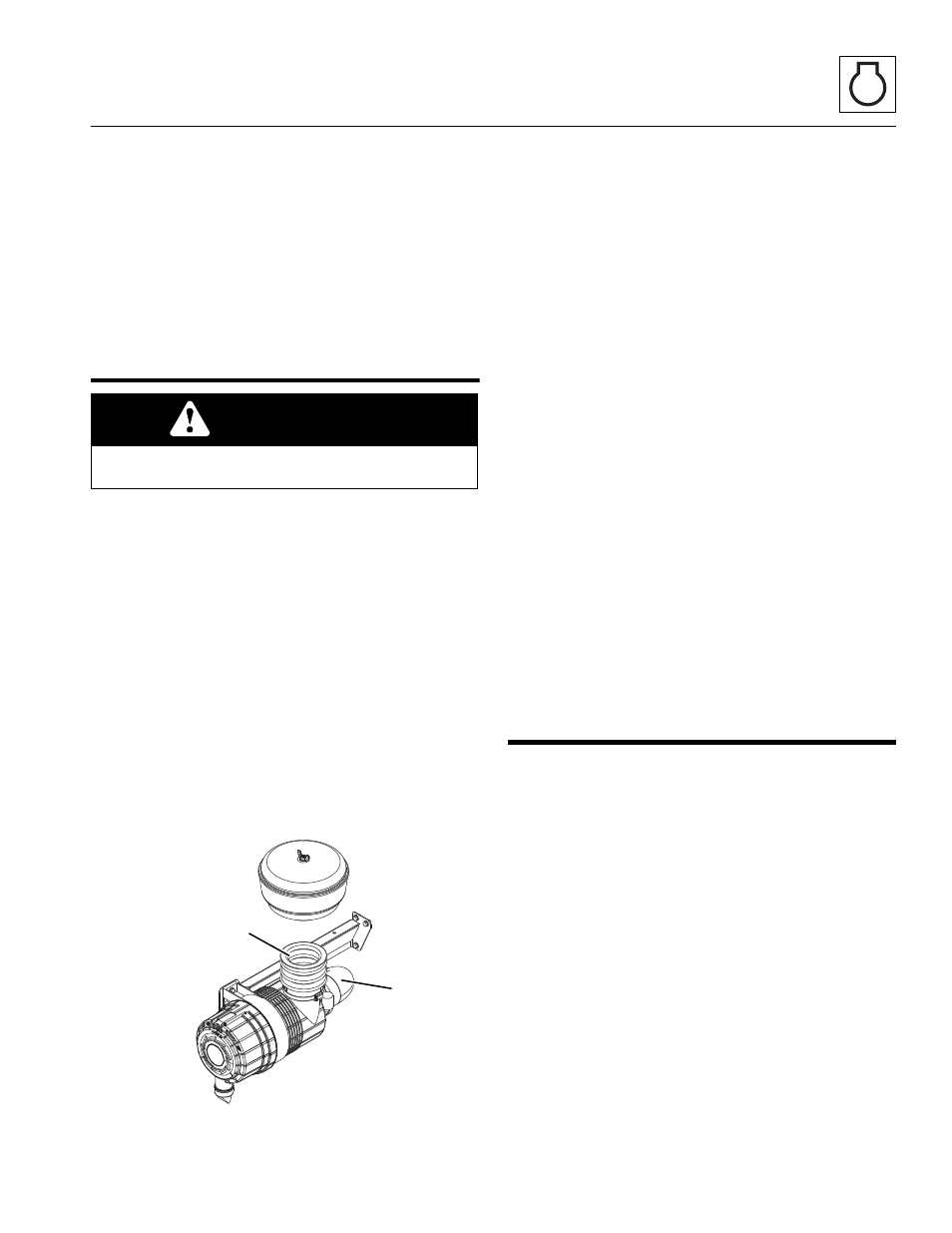
6. Remove the clamp securing the air intake boot (11)
to the air cleaner assembly. Lift the air intake boot off
the air cleaner.
7. Remove the clamp securing the air outlet elbow (12).
Lift the air outlet elbow off the air cleaner.
8. Remove the two capscrews and ripp nuts securing
the air cleaner mounting bracket to the air cleaner
mounting plate. Remove the air cleaner assembly.
7.8.2
Air Cleaner Assembly Installation
Note: Apply Loctite
®
243
TM
threadlock to the capscrew
threads before installation.
1. With the air cleaner assembly attached, install the air
cleaner mounting bracket using capscrews and ripp
nuts.
2. Place the loosened clamp over the air intake boot,
and install boot on the air cleaner assembly.
3. Place the loosened clamp over the air outlet elbow
and install elbow on the air cleaner assembly.
4. Connect low pressure indicator wire connection.
5. Adjust and tighten both clamps before starting the
machine.
6. Properly connect the battery.
7. Close and secure the engine cover.
8. Remove the Do Not Operate Tags from both the
ignition key switch and the steering wheel.
7.9
ENGINE REPLACEMENT
7.9.1
Engine Removal
1. Park the machine on a firm, level surface, level the
machine, fully retract the boom, lower the boom,
place the transmission control lever in
(N) NEUTRAL, engage the park brake and shut the
engine OFF.
2. Place a Do Not Operate Tag on both the ignition key
switch and steering wheel, stating that the machine
should not be operated.
3. Open the engine cover. Allow the engine to cool.
4. Disconnect the (+) positive and (-) negative battery
cables and remove the battery.
5. Remove the engine cover, radiator guard plate and
the engine belly pan.
6. Drain and remove the radiator assembly. Refer to
Section 7.4.3, “Radiator/Oil Cooler and Coolant
Heater Replacement.”
7. Remove the heater hoses attached to the engine.
CAUTION
NEVER run the engine with only the inner safety
element installed.
MZ2010
12
11