10 charging circuit, 1 alternator, Charging circuit – JLG 4013PS Service Manual User Manual
Page 165: Alternator
9-25
3508PS, 3509PS, 3512PS, 3513PS, 4008PS, 4009PS, 4012PS, 4013PS, 4017PS, 40.8, 40.9
Electrical System
f.
Starter Installation
1. Position the starter in its mounting opening on the
flywheel housing. Position the ground cable over the
correct starter mounting bolt. Secure the starter with
fasteners. Torque fasteners to 43 Nm (32 lb-ft).
2. Connect the positive (+) battery cable to the upper
solenoid stud. Install the wires to the upper solenoid
stud, and secure with lockwasher and nut. Torque
nuts to 43 Nm (32 lb-ft).
3. Connect the wire to the solenoid mounting stud.
4. Properly connect the battery.
5. Close and secure the engine cover.
6. Remove the Do Not Operate Tag from the ignition
key switch and the steering wheel.
9.10
CHARGING CIRCUIT
Before using a battery charger, an attempt can be made
to recharge the battery by jump-starting the machine.
(Refer to the appropriate Operation & Safety Manual.)
Allow the engine to run, which will enable the alternator to
charge the battery.
If the engine alternator charging warning indicator
illuminates, perform the following checks:
1. Check the all battery cable connections at the
battery, and verify that they are clean and tight.
2. Check the external alternator wiring and
connections, and verify that they are in good
condition.
3. Check the fan belt condition and tension.
4. Verify that the alternator mounting hardware is tight.
5. Run the engine and check the alternator for noise. A
loose drive pulley, loose mounting hardware, worn or
dirty internal alternator bearings, a defective stator
or defective diodes can cause noise. Replace a worn
or defective alternator.
9.10.1
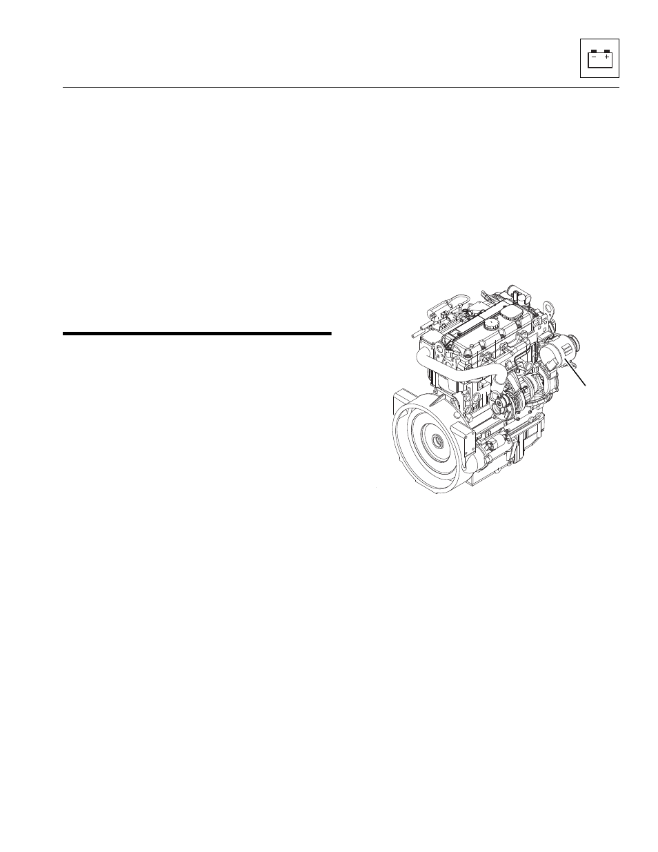
Alternator
a. Alternator Removal
1. Park the machine on a firm, level surface, level the
machine, fully retract the boom, lower the boom,
place the transmission control lever in (N)
NEUTRAL, engage the park brake and shut the
engine OFF.
2. Place a Do Not Operate Tag on both the ignition key
switch and the steering wheel, stating that the
machine should not be operated.
3. Open the engine cover. Allow the engine to cool.
4. Properly disconnect the battery.
5. Loosen both alternator (2) mounting bolts and pivot
alternator in.
6. With the fan belt now being loose, remove the belt
from the engine.
Note: Record how the alternator is installed to ensure
correct installation later.
7. Label and disconnect the wire leads attached to the
alternator.
8. Remove the lower mounting capscrew securing the
alternator to the lower mounting hole on the engine.
9. While supporting the alternator with one hand,
remove the upper (longer) mounting hardware from
the upper alternator mount. Remove the alternator
from the machine.
MZ0150
2