10 boom installation, Boom installation – JLG 4013PS Service Manual User Manual
Page 49
3-17
3508PS, 3509PS, 3512PS, 3513PS, 4008PS, 4009PS, 4012PS, 4013PS, 4017PS, 40.8, 40.9
Boom
3.6.10
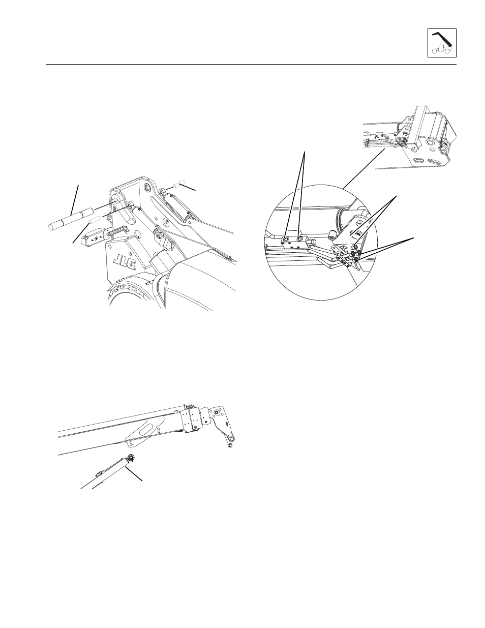
Boom Installation
Note: Light lubrication of the boom wear surfaces with a
factory authorized grease is recommended to keep the
boom wear surfaces lubricated properly. Light lubrication
of the boom wear surfaces is also recommended when
the machine is stored, to help prevent rusting.
1. Park the machine on a hard, level surface. Make
sure park brake is set, key is removed from the
ignition and “Do Not Operate” tag is placed in clear
view in the cab.
2. Using suitable slings, balance the boom assembly,
lift and carefully guide the boom into place. Align the
frame pivot bore with the boom assembly pivot bore.
Install boom pivot pin (4). Apply Loctite
®
243
TM
and
torque lock bolt to 90 Nm (66 lb-ft).
3. With the sling still in place, install both
Compensation cylinders, pins and lock bolts (5).
Apply Loctite
®
243
TM
and torque to 90 Nm (66 lb-ft).
4. With the sling still in place, install the rod end of the
Lift/Lower cylinder, pin and lock bolt (6). Apply
Loctite
®
243
TM
and torque to 90 Nm (66 lb-ft).
Note: Raising the boom up or down with the sling
maybe necessary so the boom, Compensation and Lift/
Lower cylinder bores can be aligned for easier pin
installation.
Note: Grease the boom pivot bore, compensation
cylinder rod ends, lift/lower cylinder rod end and pins
before installing.
5. Remove the caps from Extend/Retract cylinder
fittings and plugs from Extend/Retract cylinder
hoses. Attach each hose to the Extend/Retract
cylinder fittings (7) and tighten until wrench-tight.
Mark the hose fitting then tighten each hose firmly 1
to 1-1/2 flats.
6. Remove the caps from both Tilt tubes (8) and
Auxiliary tubes (9) and plugs from both Tilt hoses
and both Auxiliary hoses. Attach both sets of hoses
to the Tilt tubes and the Auxiliary tubes and tighten
until wrench-tight. Mark the hose fitting then tighten
each hose firmly 1 to 1-1/2 flats.
7. Connect the boom angle indicator rod from switch at
the inside left rear corner of the main boom section
and frame. Refer to Section 9.14.7, “Boom Angle
Sensor,” for adjustment information.
8. Start the engine and operate all boom functions
several times. Check for leaks, and check the
hydraulic oil level in the reservoir; add oil if required.
9. Clean up all debris, hydraulic oil, etc., in, on, near
and around the machine.
MZ1230
4
5
5
MZ1240
6
MZ1250
7
9
8