2 lsi sensor, Lsi sensor, Warning – JLG 4013PS Service Manual User Manual
Page 179
9-39
3508PS, 3509PS, 3512PS, 3513PS, 4008PS, 4009PS, 4012PS, 4013PS, 4017PS, 40.8, 40.9
Electrical System
• In some instances the LSI system may slow down or
stop boom functions if operated close to forward
stability limitations. When LEDs begin to flash,
function can not be operated. Retract boom and/or
return the joystick to neutral position for a short
period to allow system to reset and LEDs to stop
flashing before proceeding with operation.
Passive Mode (8 & 9M)
• The orange LED (14) illuminates when either of the
following occurs:
• The boom is fully retracted.
• The park brake is not applied and transmission
control lever is in the forward or reverse position.
• When approching forward stability limitations, visual
and audible indication is provided and the automatic
function cut-out and /or slow down feature is
disabled.
• Travel in accordance with the requirements set forth
in Section 1 - General Safety Practices.
• When placing a load, ensure axles are not fully
steered in either direction.
• Test the LSI at the beginning of each work shift.
1.Fully retract and level the boom, with no load. Do
not raise the boom during this test.
2.Level frame using level in cab.
3.Press the system check button (13) on the LSI
display. This will cause all LEDs to flash on and an
audible warning to sound. This indicates that the
system is functioning properly. If the test gives a
different result, the system is not functioning
properly and the machine must be removed from
service and repaired before continued operation.
9.16.2
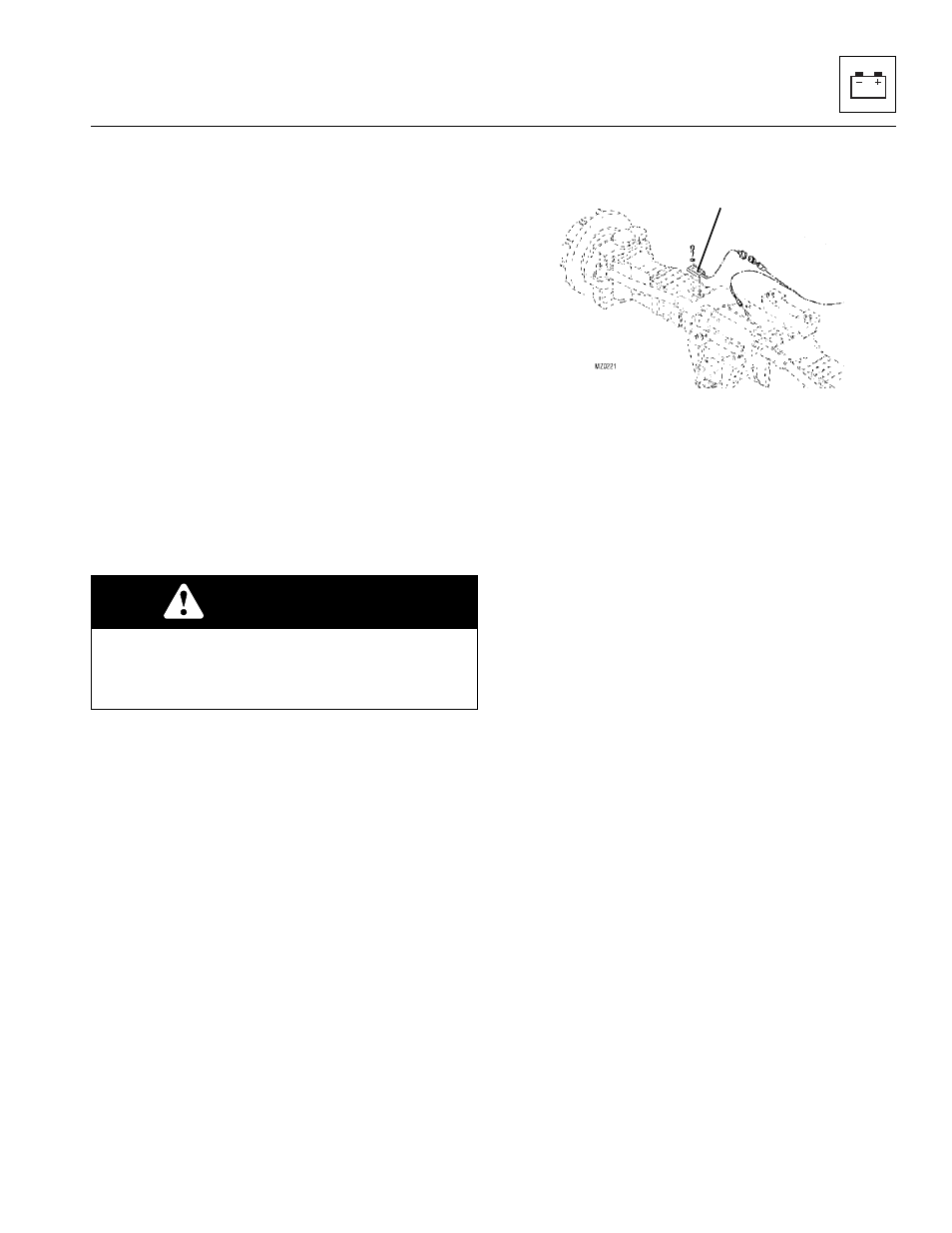
LSI Sensor
The LSI sensor (15) is bolted on the top right of the rear
axle.
Note: If the rear axle is removed or replaced, the LSI
Sensor must be installed AFTER the rear axle is installed
and setting on all four wheels.
a. LSI Sensor Removal
1. Remove any fork carrier or attachment from the
machine.
2. Park the machine on a firm, level surface, level the
machine, fully retract the boom, fully raise the boom,
place the transmission control lever in (N)
NEUTRAL, engage the park brake and shut the
engine OFF.
3. Place a Do Not Operate Tag on both the ignition key
switch and the steering wheel, stating that the
machine should not be operated.
4. Open the engine cover. Allow the engine to cool.
5. Properly disconnect the battery.
6. Disconnect the LSI electrical connector.
7. Loosen, remove and discard the two bolts holding
the LSI assembly to the rear axle.
8. Remove and discard the sensor assembly.
b. LSI Sensor Installation
1. Ensure threads of both bolt holes are clean and free
from rust, water and debris.
2. Clean the bare metal with a degreasing agent,
Loctite
®
7063
TM
.
3. Remove any excess degreasing agent and allow to
dry.
4. Apply a thin film of Loctite
®
638
TM
adhesive to the flat
metal surface of the sensor, ensuring the adhesive is
spread evenly over the entire surface.
WARNING
TIP OVER HAZARD. If the green, orange and red
LEDs flash and warning buzzer sounds, retract and
lower boom immediately. Determine cause and
correct before continued use.
15