JLG 4013PS Service Manual User Manual
Page 135
8-25
3508PS, 3509PS, 3512PS, 3513PS, 4008PS, 4009PS, 4012PS, 4013PS, 4017PS, 40.8, 40.9
Hydraulic System
3. Open the engine cover. Allow the system fluids to
cool.
4. Properly disconnect the battery.
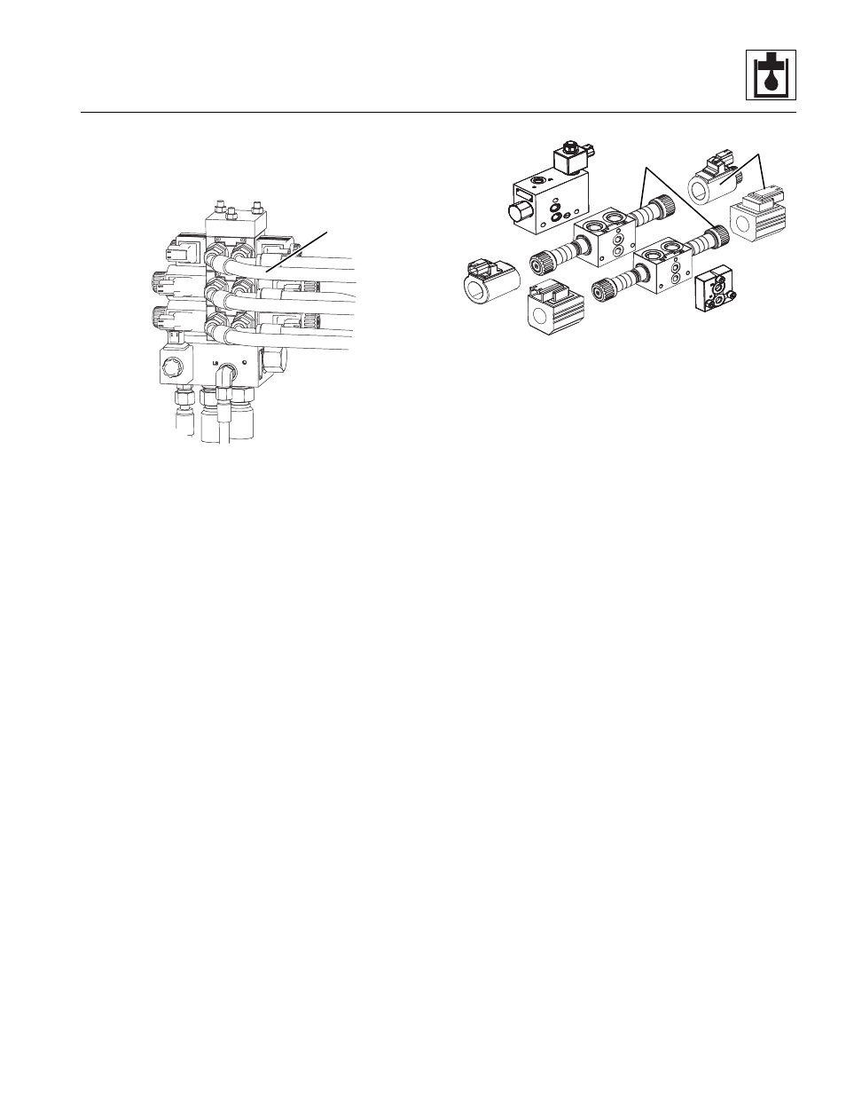
5. Label, disconnect and cap all hydraulic hoses (1)
and fittings connected to the leveling valve.
6. Disconnect all wire terminal leads attached to the
leveling valve.
7. Remove the bolts holding the leveling valve to the
engine compartment.
8. Remove the leveling valve from the machine. Wipe
up any hydraulic oil spillage in, on, near and around
the machine.
b. Leveling Valve Disassembly
1. To disassemble the individual sections of the
leveling valve, remove the nuts from one end of the
tie rods. Pull the tie rods out through the sections.
2. Disassemble each section assembly as required.
Disassemble each Valve Section
1. Carefully separate the cover plate from the next
section.
2. Remove the o-rings from between the two sections.
3. Carefully separate each remaining section.
4. Remove any coils (2) or retainers (3) from the
individual valve section.
5. Keep all parts being removed from individual valve
sections tagged and kept together.
c. Leveling Valve Parts Cleaning
Clean all components with a suitable cleaner, such as
triclorethylene, before continuing. Blow dry.
d. Leveling Valve Parts Inspection
Inspect all parts and internal passageways for wear,
damage, etc. If inner surfaces of any component DO NOT
display an ultra-smooth, polished finish, or are damaged
in any way, replace the damaged part. Often, dirty
hydraulic oil causes failure of internal seals, damage to
the polished surfaces within the component, and wear of
and/or harm to other parts.
e. Leveling Valve Assembly
Note: ALWAYS replace seals, o-rings, etc., with new
parts to help ensure proper sealing and operation.
Lubricate seals and o-rings with clean hydraulic oil.
Assemble each Valve Section
1. Reassemble any coils or retainers from each
individual valve section.
Assemble the Leveling Valve
1. Place all three tie rods with the nuts through the end
valve section.
2. Stand the end valve section on end.
3. Install the proper o-rings on the inner face of the
valve section. Align the next valve section over the
three tie rods and slide onto the end valve section.
4. Using the proper o-rings, repeat step three for the
remaining valve sections and lastly the cover plate.
5. Install the nuts on the tie rods.
MZ2280
1
13M MACHINE SHOWN
MZ2410
2
3