4 quick switch removal, 5 quick switch installation, 12 forks – JLG 4013PS Service Manual User Manual
Page 59: Forks, Quick switch removal, Quick switch installation
3-27
3508PS, 3509PS, 3512PS, 3513PS, 4008PS, 4009PS, 4012PS, 4013PS, 4017PS, 40.8, 40.9
Boom
3.11.4
Quick Switch Removal
1. Support the quick switch assembly. Remove the lock
bolt (11) holding the tilt cylinder rod end pin (12) to
the quick switch assembly. Remove the tilt cylinder
pin.
2. Support the quick switch assembly. Remove the four
bolts and covers (13) from each end of the quick
switch assembly. Remove the pin from the quick
switch assembly from either side.
3. Inspect the above pin for nicks or surface corrosion.
Use fine emery cloth to fix minor nicks or corrosion.
If damaged or if it cannot be repaired, the pin must
be replaced.
3.11.5
Quick Switch Installation
1. Assemble the quick switch to the boom head. Line
up the quick switch between the mounts on the
boom head. The quick switch should be centered in
the boom head.
2. Coat the quick switch pivot pin with an anti-seize
compound. Insert the quick switch pivot pin through
the quick switch and boom head. Replace the end
covers and four bolts (10) to each end of the quick
switch.
3. Align the quick switch with the tilt cylinder rod end
and insert the tilt cylinder pin. Align the tilt cylinder
pin and screw in the locking bolt (9). Torque as
required.
3.12
FORKS
Forks should be cleaned and inspected prior to being
attached to carriage. If the following criteria is not met,
forks must be removed from service immediately.
Daily Inspection
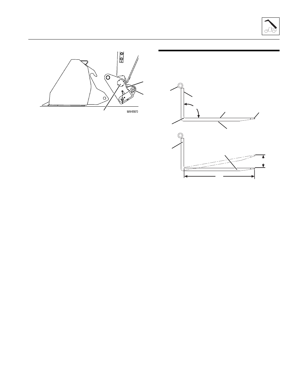
1. Inspect forks (1) for cracks, paying special attention
to heel (2) and mounting tubes (3).
2. Inspect forks for broken or bent tips (4) and twisted
blades (5) and shanks (6).
Yearly Inspection
1. Straightness of the upper face of blade (5) and the
front face of shank (6) should not exceed 0.5 percent
of the length of blade or height of shank.
2. Angle (7) between upper face of blade and front face
of shank should not exceed 93 degrees.
3. Thickness of blade (8) and shank (9) should not be
reduced to 90 percent of original thickness.
Note: Contact the local distributor with the fork part
number to find the manufactured dimensions of the fork
blade.
4. Ensure fork length (10) is adequate for intended
loads.
5. Fork markings should be legible, re-stamp if
required.
6. Compare fork tips (11) when mounted on a carriage.
Maximum difference in height of fork tips is 3 percent
of the length of the blade (10).
13
12
11
MH6460
3
2
6
7
5
1
4
9
8
10
11