2 installing wheel and tire assembly onto machine, 6 brakes, 1 brake disk inspection – JLG 4013PS Service Manual User Manual
Page 85: Brakes, Installing wheel and tire assembly onto machine, Brake disk inspection, To section 5.6, “brakes
5-11
3508PS, 3509PS, 3512PS, 3513PS, 4008PS, 4009PS, 4012PS, 4013PS, 4017PS, 40.8, 40.9
Axles, Drive Shafts, Wheels and Tires
5.5.2
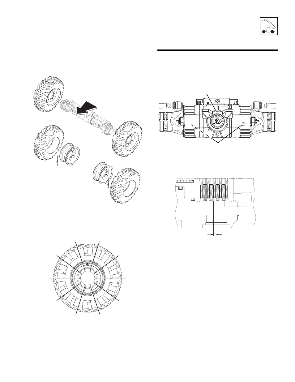
Installing Wheel and Tire Assembly
onto Machine
Note: The wheel and tire assemblies must be installed
with the directional tread pattern “arrows” facing in the
direction of forward travel.
1. Position wheel onto studs on wheel end of axle.
2. Install wheel lug washers.
3. Start all nuts by hand to prevent cross threading. DO
NOT use a lubricant on threads or nuts.
4. Tighten lug nuts in an alternating pattern as
indicated in figure. Torque to 575 Nm (424 lb-ft).
5. Remove machine from supports.
6. Remove the Do Not Operate Tags from both the
ignition key switch and the steering wheel.
5.6
BRAKES
5.6.1
Brake Disk Inspection.
a. Front and Rear Axles
1. Block all four wheels to help prevent the machine
from moving after the parking brake is disabled.
2. Remove the oil-level plug (6) on each side of the
axle.
3. Have an assistant sit in the cab and apply the
brakes, keeping pressure applied.
4. Using a feeler gauge, check the gap between the
brake discs (7). If the gap is less than 4,5 mm
(0.18 in), replace the brake discs.
Note: If the brake discs are worn beyond their
tolerance, the brake disc must be replaced on both sides
of the axle at the same time.
5. Repeat steps 3 and 4 for the other side of the axle.
6. Fill the axle through the axle fill plug (8) until the oil
level is even with the oil check level plugs (6). Refer
to Section 2.4, “Fluids, Lubricants and Capacities,”
for proper oil and capacities.
Mh3300
Tread "arrows" must point
forward
Install tires onto wheels to
rotate in proper direction
MY4200
1
3
8
6
9
4
10
5
2
7
MZ1030
6
8
MZ5830
7