JLG 4013PS Service Manual User Manual
Page 177
9-37
3508PS, 3509PS, 3512PS, 3513PS, 4008PS, 4009PS, 4012PS, 4013PS, 4017PS, 40.8, 40.9
Electrical System
Field Calibration Procedure:
Note: If the test weight is not known, follow steps 1 & 2.
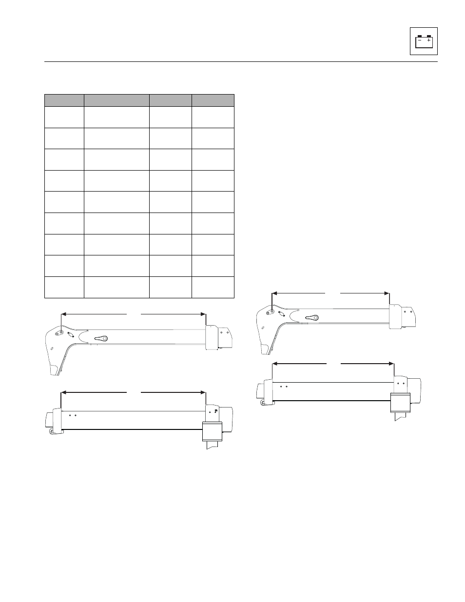
1. With the estimated test weight on the forks, start the
machine and extend the boom horizontally until the
machine starts to tip. This point should be at an
extension of Xtip (1) of the second boom section. If
the machine is not tipping at this extension, weight
needs to be added or removed from the forks.
2. By confirming that the machine tips at this point, the
correct amount of weight is now on the forks.
3. The machine control system must be powered on for
at least 10 minutes before calibration.
4. Retract the boom and place the test weight on the
ground. Disengage the weight and fully retract the
lower the boom.
5. Ensure the boom is level and fully retracted, the
forks are level and not contacting the ground. Apply
the park brake and shut engine OFF.
6. With the ignition key in OFF position, press and hold
TEST button on LSI display and turn ignition key to
engine START position. Release the ignition key
when engine start is achieved, but continue to hold
TEST button on LSI display until the LED power
indicator on LSI display begins to flash
(approximately 2 seconds).
7. Release TEST key within 2 seconds of power LED
flashing. The lower green LED of the scale should
be on constant.
8. Press the TEST button on the LSI display and
release. The lower green LED should flash for
approximately 8 seconds while the calibration point
is read. Following successful calibration of the first
point, the buzzer will sound for 2 seconds, the green
LED will be turned off, and the top red LED will be on
constant.
9. Without moving the machine, pick up the proper test
weight (W) listed in the table on page 9.39. Ensure
the forks are no more than 152 mm (6 in) off the
ground.
10. With the boom horizontal, slowly extend the boom to
the distance of Xcal (2). The proper calibration
weight is now on the rear axle and the LSI can now
be calibrated.
Model
Test Weight (W)
Xtip (1)
Xcal (2)
3508PS
2100 kg
(4630 lb)
2300 mm
(90 in)
1620 mm
(64 in)
3509PS
2000 kg
(4409 lb)
3030 mm
(119 in)
2060 mm
(81 in)
3512PS
500 kg
(1102 lb)
2985 mm
(117 in)
2100 mm
(83 in)
3513PS
500 kg
(1102 lb)
3275 mm
(129 in)
2310 mm
(91 in)
4008PS,
40.8
2100 kg
(4630 lb)
3107 mm
(122 in)
2372 mm
(93 in)
4009PS,
40.9
2000 kg
(4409 lb)
3700 mm
(146 in)
2840 mm
(112 in)
4012PS
700 kg
(1543 lb)
3145 mm
(124 in)
2340 mm
(92 in)
4013PS
700 kg
(1543 lb)
3535 mm
(139 in)
2655 mm
(105 in)
4017PS
500 kg
(1102 lb)
2715 mm
(107 in)
2070 mm
(81 in)
MAM1470
A
B
C
D
A
B
C
1
3512PS, 4012PS, 3513PS, 4013PS & 4017PS
3508PS, 4008PS, 3509PS, 4009PS, 40.8 & 40.9
1
A
B
C
MAM1480
A
B
C
D
2
2
3508PS, 4008PS, 3509PS, 4009PS, 40.8 & 40.9
3512PS, 4012PS, 3513PS, 4013PS & 4017PS