Dimensional data, Chassis, 5 torque requirements – JLG 1100SB Service Manual User Manual
Page 18: Dimensional data -2 chassis -2, Torque requirements -2, Dimensional data -2, Chassis specifications -2, Engine torque requirements -2, Dimensional data chassis 1.5 torque requirements
SECTION 1 - SPECIFICATIONS
1-2
– JLG Lift –
3121265
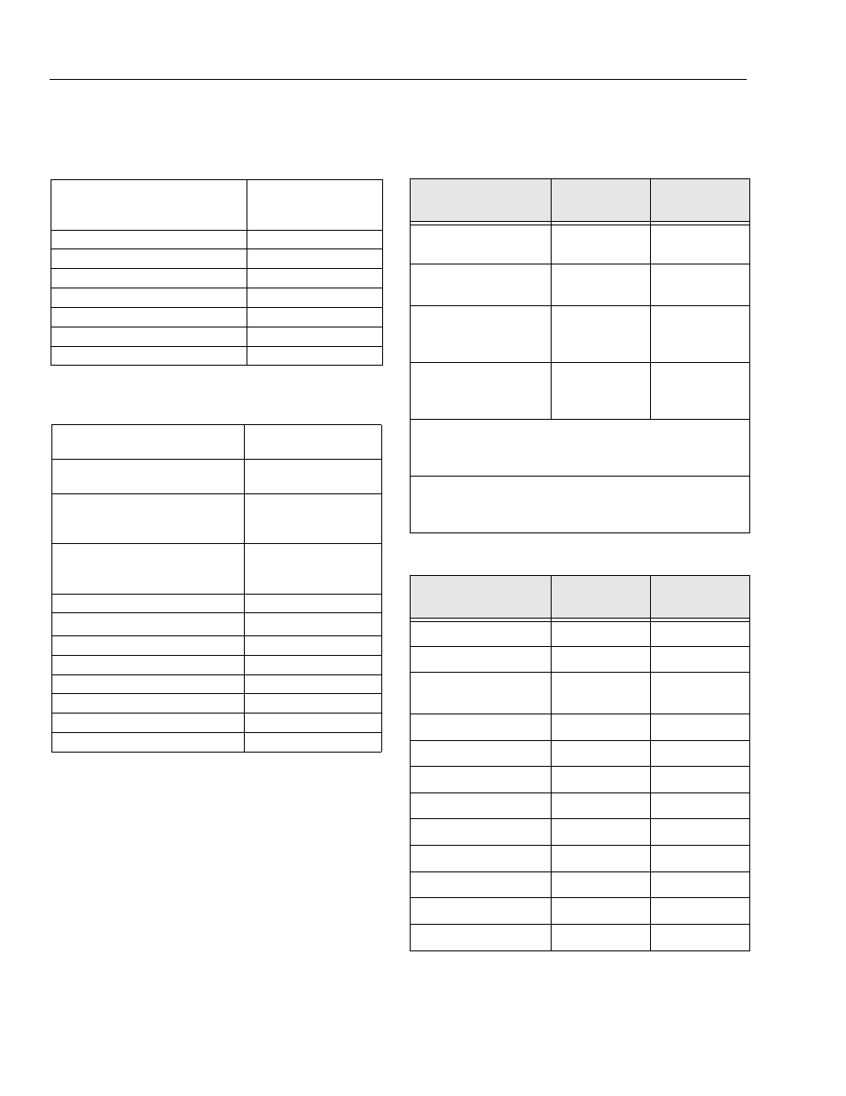
Dimensional Data
Chassis
1.5 TORQUE REQUIREMENTS
Table 1-5. Dimensional Data
Overall Width
Axles Retracted
Axles Extended
8 ft. 2in. (2.49 m)
12 ft. 6in. (3.8 m)
Stowed Height
10 ft. (3.04 m)
Stowed Length (Transport Mode)
38 ft. 11in. (11.86 m)
Stowed Length (Working Mode)
48 ft. 11in. (14.91 m)
Wheelbase
12 ft. 6in. (3.81 m)
Tailswing
5 ft. 6 in. (1.6 m)
Ground Clearance (Axle)
12 in. (30.4 cm)
Ground Clearance (Chassis)
25.5 in. (64.7 cm)
Table 1-6. Chassis Specifications
Maximum Travel Grade With boom in
stowed position (Gradeability)
45%
Maximum Travel Grade With boom in
stowed position (Side Slope)
5°
Turning Radius (Axles Retracted)
Outside
Inside
22 ft. 6 in. (6.8 m)
14 ft. 5 in. (4.4 m)
Turning Radius (Axles Extended)
Inside
Outside
8 ft. (2.4 m)
19 ft. 4 in. (5.9 m)
Max Tire Load
26,250 lbs. (11,907 kg)
Max Ground Bearing Pressure
105 psi (7.38 kg/cm
2
)
Maximum Drive Speed
3.25 mph (5.2 kph)
Max. Hydraulic System Pressure
4600 psi (317 Bar)
Maximum Wind Speed
28 mph (12.5 m/s)
Maximum Manual Force
400 N
Electrical System Voltage
12 Volts
Gross Machine Weight (Platform Empty)
44,750 lb. (20,298 kg)
Table 1-7. Torque Requirements
Description
Torque Value
(Dry)
Interval Hours
Wheel Bolts
180 ft. lbs.
(252 Nm)
150
Swing Bearing Bolts
240 ft. lbs.
(336 Nm)
50/600*
Tele Cylinder
Regen Valve Mounting
Bolts
13 ft. lbs.
(18 Nm)
As required
Starter Solenoid
Contacts
Coil
95 in. lbs. (9.5 Nm)
40 in. lbs. (4 Nm)
As required
*Check swing bearing bolts for security after first 50 hours of
operation and every 600 hours thereafter. (See Swing Bear-
ing in Section 3.)
NOTE: When maintenance becomes necessary or a fas-
tener has loosened, refer to the Torque Chart to
determine proper torque value.
Table 1-8. Engine Torque Requirements
Description
Torque Value
Ft. Lb.s
Torque Value
Nm
Cylinder Head Cover
6
8.5
Cylinder Head Cover
6
8.5
Rocker Arm Adjustment
Screw
15
21
Intake Manifold
6
8.5
Air Intake Pipe
15
21
Exhaust Manifold
16
22
Oil Drain Plug
39
55
Oil Pan (sheet metal)
15
21
Oil Pan (cast)
22
31
Injection Line Attachment
21
30
Injection Valve Attachment
15
21
Lube Oil Filter Cartridge
19
27