Aerovent IM-201 User Manual
Page 9
Aerovent IM-201
9
6.8 SETTING MAXIMUM PITCH ON FPAC
& FPMC FANS
If it should become necessary to adjust the maximum
blade pitch on thee fans, proceed as follows:
1. Remove vane access section as per Section 5.7.
2. Release the two lock nuts on each stud (10) to allow a
change in their position.
a. Set a protractor at the desired blade angle, 45°-47°, etc.
b. Bring fan to maximum pitch. Have the nuts on the studs
at same distance to start (item 21, near hub on Figure 6
in the AXICO instruction manual).
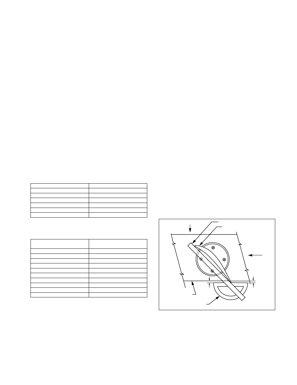
c. Check angle by placing the blade of the protractor
(scale) across the root (base) of the blade. When the
proper angle is found, the base of the protractor should
be parallel to the edge of the fairing. See Figure 5.
d. Adjust by turning stop nut (#21). Be sure that both
springs are compressed solid at the same time or the
spider will hang up on the hub.
NOTE: The fairing is scribed with a line that represents the
maximum blade angle that was set at the factory. This mark
can be used as a reference to check the angle. Factory blade
angle is indicated on nameplate.
CAUTION: Do not set maximum pitch stops at a blade angle
higher than 55°.
6. Tighten each locking nut.
7. Reassemble the vane access section.
6.9 MINIMUM PITCH SETTING
Aerovent AXICO fans may have minimum pitch set-
ting accomplished by use of two extended bolts in the dia-
phragm cover. This may be used to prevent the flow of any
system from going below a certain specified minimum.
Size 125 and larger have minimum pitch stops as stan-
dard set, if not otherwise specified, to 0 flow. Consult factory
for specific details on specific fans.
Figure 5.
Protractor Blade Scale
Base of Blade
Rotation
Airflow
Protractor Base
Fairing Edge
=
=
c. Replace the nuts on the studs, maintaining the position
recorded when they were removed. Tighten each jamb
nut to 24 ft-lbs.
6.5 ROTOR INSTALLATION
If the rotor has been removed from the shaft, obvious-
ly it must be put back in place prior to attaching the diaphragm
cover to hub cover as described above. To install the rotor on
the shaft, proceed as follows:
1. Clean fan shaft with solvent and apply a film of grease.
Locate key in keyway.
2. Slide rotor on fan shaft.
NOTE: It may be necessary to use a bar and a
1
∕
2
"-13 UNC
stud threaded into the motor shaft with a nut to pull the
rotor on the shaft.
3. Clean bolt and shaft threads and prime with Loctite grade
T primer. Blow out internal threads with air and allow to
air dry 5 minutes. Apply Loctite 242 to threads.
4. Install washer and bolt and torque to 50 ft-lbs for
1
∕
2
" bolt;
15 ft-lbs for
3
∕
8
" bolt.
5. Proceed with remainder of assembly depending on fan
type per Section 6.4.
6.6 MOTOR BOLT TORQUE
Motor bolts should be torqued to the following speci-
fications. Remember that it is not possible to check a torqued
bolt unless it is loosened first, as torque must be applied evenly
until the desired torque is reached. To tighten further after
a given torque value has been reached requires much more
torque to get the nut started than will be required to keep
tightening it, so the desired final torque must be reached in
one movement. All bolts are grade 5.
6.7 MINIMUM BLADE TIP CLEARANCE
The following dimension is the minimum clearance
between the tip of any blade and the fan case.
BOLT SIZE
TORQUE (FT-LBS)
5
⁄
16
-18
13
3
⁄
16
-16
27.5
1
⁄
2
-13
75
5
⁄
8
-11
150
3
⁄
4
-10
240
7
⁄
8
-9
380
FAN SIZE
MIN. TIP
CLEARANCE (IN.)
071
.030
080
.030
090
.034
100
.038
112
.043
125
.049
140
.055
160
.063
180
.072
200
.080