Aerovent IM-201 User Manual
Page 2
2
Aerovent IM-201
2.2 LIFTING
Aerovent fans should be lifted using slings. Note that
on AXICO fans the slings should be placed under the skids,
and spreader bars used as required. Under no circumstances
should the vane section be used for lifting.
2.3 MOUNTING
Depending on the type of fan support specified, the
fan can be floor mounted on legs, supported on a structural
frame or ceiling hung if clips or support brackets are included,
and again supported on the floor on a frame, or ceiling hung
if the fan is for vertical airflow.
2.3.1 Vibration Isolators
The fan is dynamically balanced to reduce vibration to
a low level. However, it is recommended that the fan be sup-
ported on vibration isolators. Isolators should be selected for
each installation in accordance with individual requirements.
The weight distribution between mounts is not equal
on Aerovent fans. Consult the factory for isolator selection
or mount loads. Isolators should be selected to support the
unequal load with equal deflection. A subbase can be used
to equally distribute the load to the isolators. Concrete inertia
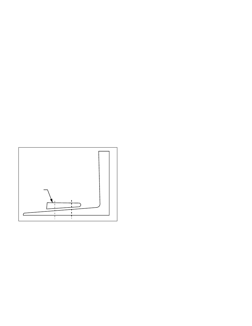
pads are generally not required on Aerovent axial fans. When
mounting isolators or tie-down bolts through the base frame
of an Arrangement 4 Type 3 fan, it is recommended that you
use a beveled washer between the base frame and the nut. See
Figure 1.
Figure 1.
2.3.2 Fan Reactions
It is essential to minimize fan movement due to start-
ing torque and air thrust force. These forces must be resisted
to maintain duct alignment and prevent damaging the flexible
connectors. Isolators must be selected with adequate stiffness
to resist these forces. Snubbers may be required in some instal-
lations to limit the fan movement.
2.4 DUCT CONNECTIONS
All fans should be closely aligned with the ductwork. A
flexible connection should be provided between the fan and
duct to prevent structure-borne noise from being transmit-
ted to the ductwork. Use band clamps and seal with Borden’s
Arabol, or equal, to insure mechanical security and prevent
leakage on all flexible connections.
NOTE: Provide a 1-inch to 2-inch gap between the fan
and duct to allow for fan movement.
2.4.1 Diffuser and Cone Connection
On AXICO fans, the standard discharge is not intend-
ed to be directly connected to the fan vane section. Support
the diffuser independently of the fan and provide a flexible
connection between the fan and the diffuser. On all Aerovent
fans, inlet cones can be directly connected and they also
become part of the load to be isolated.
2.4.2 Inlet Bell Connection
The inlet bell may be mounted in a plenum wall with a
flexible connection between the outer edge of the bell and a
hole in the partition. Provide a 2-inch to 3-inch gap to allow
for fan movement.
The inlet bell may be installed protruding into the ple-
num where space is limited. A metal ring should be installed
between the inlet bell and the case flange and a flexible con-
nection installed between the ring and the plenum wall.
2.5 ELECTRICAL
All wiring should conform to local electrical codes and
the job specification.
2.5.1 Power Connection
The motor leads terminate in the conduit box. The
leads are factory connected for the voltage specified for the
job. Motor leads for wye-delta and part-winding starts are
not connected. Rigid conduit should be run from the motor
starter to the fan with a short section of flexible conduit at the
conduit box to allow for fan movement.
Wire size and motor overloads should be sized in
accordance with the fan nameplate electrical data. The conduit
box is located on the outside of the case on all ducted, direct
driven fans. If the motor is outside the fan case, connection
will be made directly to the motor.
2.5.2 Motor Rotation
Check motor rotation by jogging the motor. The rota-
tion should be clockwise when viewed from the inlet of the
fan. Reverse any two motor leads to change rotation.
NOTE: It is important that correct motor rotation be
established on ducted fans as the rotor will not be visible after
an inlet duct is installed.
2.5.3 Electrical Data
If the fan is a variable pitch AXICO fan, it is recom-
mended that the fan not be run until the controls are opera-
tional. The fan should be started in accordance with Section
2.5.4 and the electrical data measured and compared to motor
nameplate ratings.
2.5.4 Final Check Before Putting
Fan Into Operation
1. Check for correct supply voltage and motor overloads.
2. Insure that all loose debris is removed from fan, fan
room, plenum and/or all ducts.
3. Check that motor bolts are tight and rotor is centered in
fan case with adequate blade tip clearance all- around. See
Section 6.6 for motor bolt torque data, and Section 6.7 for
minimum blade tip clearance.
4. Hand rotate and then bump the fan starter to check rota-
tion.
5. Start the fan and verify that the vibration is acceptable.
If the fan is a variable pitch AXICO, make the following
additional checks.
6. Check that the air supply pressure is correct (60 to 100
psig).
Beveled
Washer