Aerovent IM-201 User Manual
Page 7
Aerovent IM-201
7
Note: If the spider is the old style that uses grease,
apply 4 to 5 strokes of a grease gun to the grease fitting behind
the spider. This will lubricate the spider hub sliding joint.
Before closing up the access panel, operate the control to cycle
the pitch several times to insure all parts move smoothly.
Every two years it is recommended that you replace
the rotary union with a new one. The longevity of the union
is dependent on the quality of the compressed air supply, and
it is a simple precaution to replace it while it is accessible.
CAUTION: Use Loctite 242 on the two screws hold-
ing the flexible cable bar to the rotary union at any time these
screws are removed and replaced.
This operation should take no more than 1 to
2 hours per fan.
5.7 VANE SECTION ACCESS
Both the FPAC and FPMC fans have removable access
sections in the vane section. This provides enough visibility
and working space for all maintenance short of removing the
fan rotor from the motor shaft.
To remove the access sections, proceed as follows:
1. Remove the flexible duct connection between the vane sec-
tion and the diffuser or duct.
2. Remove the
1
∕
4
" bolts at the side of the vane section and
remove the
1
∕
2
" washers and bolts at the flange of the
access panel.
3. Remove the panel exposing the internal stator vanes.
4. Remove the
1
∕
4
" bolts from the side of the inner case.
5. Remove the inner core access panel with the three vanes
welded to it. The interior of the vane section and the oper-
ating mechanism of the rotor is now accessible.
6.0 ROTOR REPAIR & REMOVAL
(Not Required For Maintenance)
6.1 ACCESS TO ROTOR
FPAC Fan
1. Remove the access section as described in Section
5.7.
2. Remove the air line from the rotary union.
3. Remove the two screws holding the flexible cable
bar to the rotary union.
4. Remove the
1
∕
2
" nuts and washers around the vane
section flange while supporting the vane section.
5. Slide the vane section off the fan case and remove
it sideways. The rotor is now removable.
This operation should take no more than 1 to
2 hours per fan.
FPMC Fans
1. Remove the clevis pin in the vane section core.
2. Remove the drive linkage to the operator, if used.
3. Remove the clevis pin between the bar linkage and
the fixed bracket on the fan. The bar can remain in
the vane section.
4. Proceed with steps 4 and 5 as described above for
FPAC vane section removal.
6.2 ROTOR REMOVAL
(Not Required For Maintenance)
If the rotor is to be removed from the motor shaft,
proceed as follows:
FPAC Rotor
Refer to Figure 6 for item identification.
1. Measure and record the distanced from the end of
the stud (10) to the stud bar (26).
CAUTION: This distance must be maintained at
assembly to set the maximum pitch.
2. Remove the nuts (21), stud bar, and springs (11)
from the studs.
3. Remove the bolts (15), diaphragm cover (1) and
diaphragm (8) from the spider (2).
CAUTION: Mark the position of the diaphragm cover
with respect to the spider so that it can be installed cor-
rectly and rotor balance be maintained.
4. The motor shaft bolt (32) is now visible. After
removing it, the rotor can be pulled off the motor
shaft. Two threaded holes are provided in the face
of the hub to anchor a puller bar.
FPMC Rotor
Refer to page 13 for item identification.
1. Measure and record the distance from the end of
the stud (10) to the first locknut (21).
CAUTION: This distance must be maintained at
assembly to set the maximum pitch.
2. Remove the nuts (21) from the studs.
3. Remove the bolts (15) around the hub cover (59)
and take the cover off.
CAUTION: Mark the position of the diaphragm cover
with respect to the spider so that it can be installed cor-
rectly and rotor balance be maintained.
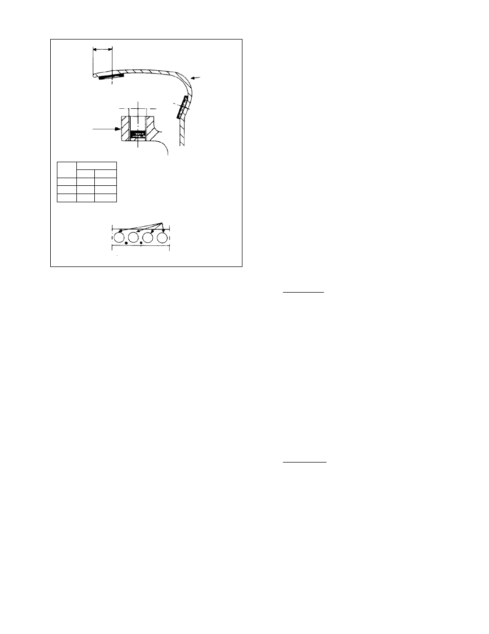
Figure 4.
Flow Section
Hub
A
B
Holes For Blades
Balancing Weights
MAX. WT. (g)
HUB
A
B
500
70
150
630
70
150
800
70
150
The balancing weights permitted at Position
A are located according to Figure 4 below.
Maximum permitted weight for each place
according to the tables above. Note that
only one hole may be drilled between the
holes for the blades.