0 maintenance – Aerovent IM-201 User Manual
Page 6
6
Aerovent IM-201
5.0 MAINTENANCE
5.1 GENERAL
Aerovent fans are a quality product designed and
manufactured for minimum maintenance and long operating
life. They should provide years of trouble-free service if the
following maintenance procedures are followed.
Aerovent fans are balanced at the factory to the fol-
lowing standards. NEMA has set standards for motor balance
which are also shown. Bearing life and lubrication require-
ments are based on the NEMA standard. The more stringent
Aerovent standards allow for normal build-up of dirt on
rotors; use, evaporation and/or shifting of lubricants; and
normal wear. If a fan appears to be out of balance, it is wise
to clean and grease before attempting to balance as this may
resolve the situation in the simplest manner.
In the event that the fan does not require dynamic bal-
ancing, balancing weights should be added as described in this
text.
Balance weights should be located only between the
blade hole openings and on the front and rear of the hub fair-
ing. See Figure 4.
Balance weights should not exceed the weight (in
grams) listed in Figure 4.
5.2 MOTOR LUBRICATION
Motor bearings do not require initial lubrication unless
the fan has been in storage over six months. If this is the case,
the motor should be lubricated initially.
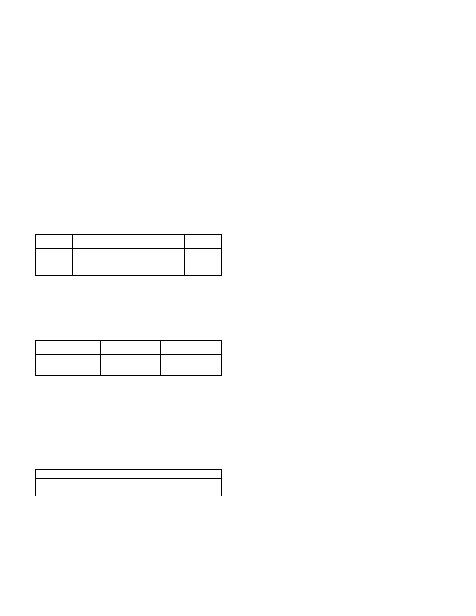
Lubricate motor bearings with grease gun at the follow-
ing intervals and numbers of strokes:
NOTE: Normal amount of grease delivered by a hand car-
tridge type grease gun.
Use only the following lubricants or their equal:
Chevron SR-2
A.F. No.2
Precision No. 2
Shell Gadus S2 V100 2
Starfak H, M and No. 2
Mobilith AW2
Mobil Grease #77
The grease fittings must be clean to prevent contamination.
The fittings are located as follows:
CAUTION: Do not over lubricate bearings or use a grease
other than specified.
5.3 AXICO FAN LUBRICATION
5.3.1 Rotor
Rotor lubrication is described in Section 5.6 under
Routine Maintenance.
5.3.2 AXICO FPMC Lubrication
In addition to the above in Section 5.3.1, all FPMC
rotors have a thrust bearing in the hub cover. The grease lead
to this bearing is on the outside of the vane section. Grease
as per Section 5.2 should be applied, one stroke once a month
of fan usage.
The FPMC unit with handwheel adjustment has a
grease fitting on the jack inside the vane section in addition
to the thrust bearing. Unless the pitch is changed frequently,
there is no reason to lubricate this more often than as part of
the two-year maintenance procedure.
The FPMC unit with external electric operator requires
lubrication with SAE 30 motor oil at the pivot joints on the
linkage every six months. The actuator requires no lubrica-
tion.
5.4 AIR LEAKS ON AXICO FPAC FANS
If, during the monthly check, an AXICO FPAC fan is
found to be acting erratically, and if the problem is not in the
external control (indicated by a constant varying 3 to 15 psig
input signal), then check for air leaks.
Listen with your ear close to the positioner. If there
is an erratic sound of air escaping when the fan is at maxi-
mum pitch, replace the pilot on the positioner (part number
F10046301).
If the pressure to the diaphragm will not hold at the
same level as main air pressure when the control pressure is
15 psig, inspect for an air leak between the positioner and
the rotor. Shut the fan off, but maintain pressure to the dia-
phragm, and proceed as in Section 5.7 to remove the access
door to the vane section. Check the air line, the diaphragm
cover bolts, and the rotary union for leaks (turn fan by hand
to detect rotary union leaks).
If the rotary union is removed or replaced with a new
one, use Loctite Stainless Steel PST on the threads going into
the diaphragm cover.
5.5 SIX-MONTH INSPECTION
AND MAINTENANCE
The motor bearings may require lubrication depending
on motor size per Section 5.2.
The FPMC fan linkage should be lubricated per Section
5.3.2.
5.6 ANNUAL AND TWO-YEAR MAINTENANCE
A minor inspection of the AXICO rotor is required
every two years, but recommended each year for continuous
duty fans or fans operating with dirty or contaminated air.
Remove the access panel of the vane section as described in
Section 5.7 and inspect the blade links to be sure the spherical
bearings are not binding, and apply an aerosol lubricant such
as CRC or WD-40.
Grease blade shaft bearings by applying grease through
the fitting in the bearing housing until excess grease comes
past the seal. Wipe away excess.
RPM
AEROVENT
SHUT-
MILS
STANDARD
DOWN
ALARM
3600
0.6 Mils Peak/Peak
2.20
1.42
1800
0.8 Mils Peak/Peak
4.40
2.84
1200
1.2 Mils Peak/Peak
6.70
4.26
900
1.6 Mils Peak/Peak
8.90
5.60
HORSEPOWER
PERIOD
STROKES
(SEE NOTE)
5 to 7
1
⁄
2
12 Month
1
10 to 40
6 to 12 Month
3
50 to 150
6 Month
3
TYPE FAN
LOCATION
Arrangement 4, Type 2
Fan case adjacent to conduit box
Arrangement 4, Type 3
End of motor base