0 axico fan blade adjustment – Aerovent IM-201 User Manual
Page 3
Aerovent IM-201
3
7. Set controller at a low set point for minimum pitch (3 psig
branch pressure to the positioner) for direct acting.
8. Verify once again that the vibration is acceptable.
9. Increase the set point for maximum pitch and measure
motor current. Check that full load current does not
exceed motor nameplate data. Also verify that the vibra-
tion level at full pitch is acceptable.
10. Verify that blade pitch changes smoothly throughout
the full range as the controller set point is moved. If the
AXICO fan has an electric operator, follow the same pro-
cedure except of course varying the signal input circuit to
the Honeywell electric opener.
3.0 AXICO FAN BLADE ADJUSTMENT
3.1 FPAC FAN
The FPAC fan has a pneumatic diaphragm incorpo-
rated in the hub to operate the blade pitch changing mecha-
nism. Air is supplied to the diaphragm through a rotary union
connected to a valve positioner mounted n the vane section.
The positioner is mechanically connected to the diaphragm by
a flexible cable.
3.1.1 Positioner — Function
The function of the positioner is to modulate the air
pressure to the diaphragm in response to the control pressure.
By means of the mechanical feedback it can sense the blade
pitch and thus satisfy the control set point. The positioner will
provide linear response to the control pressure.
The positioner is factory set to operate in the direct act-
ing mode. This means that a decreasing control pressure will
cause a decrease in blade pitch and less airflow.
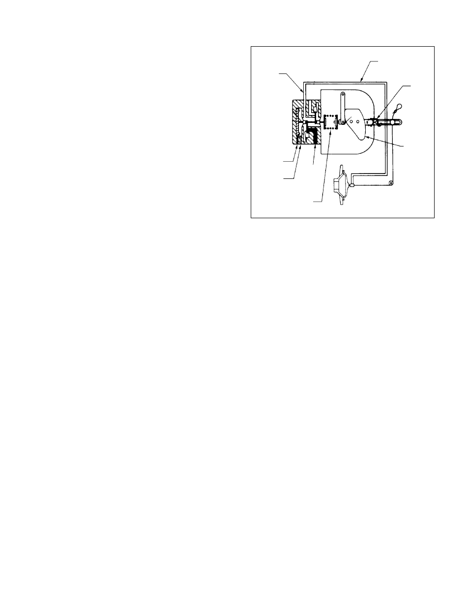
3.1.2 General Description of How It Works
The pilot positioner is a single acting, singe-stage,
force-balance type control device. Mounted on an AXICO
fan, and cable-connected to the rotor operating mechanism, it
uses an auxiliary air supply and a feedback cam controlled by
the cable to position the rotor mechanism in accordance with
the 3-15 psig air signal from the controller.
Figure 2 is a schematic diagram of this system.
Remember that the feedback spring maintains upward pres-
sure on the positioner arm at all times, and this keeps the
cable in tension. Since the positioner is direct acting, a 3 psig
instrument gauge pressure results in 0 psig valve gauge pres-
sure or minimum pitch position. When the instrument gauge
indicates 15 psig, this results in maximum valve pressure and
thus maximum pitch. The tendency of the fan blades is to go
to minimum pitch, so that, when the diaphragm pressure is
reduced, the spider will move towards the rotor, pulling the
positioner arm down and compressing the feedback spring.
3.1.3 Positioner Connections
There are three
1
∕
4
" NPT ports on the positioner. The
top port is connected to the diaphragm on the fan rotor.
The middle port should be field connected to the controller
(branch line). The bottom port should be field connected to
main air supply.
Supply air should be clean and dry instru-
ment air. Moisture or dirt in the supply air will cause
the pilot on the positioner to malfunction after repeated
exposure. The supply pressure to the positioner should be
regulated as required to achieve full pitch. The supply pressure
needed is a function of fan speed and size.
3.1.4 Positioner Calibration and Adjustment
The positioner is factory calibrated and no further
adjustment is normally required. The calibration can be eas-
ily checked and corrected if normal fan control cannot be
achieved. The positioner must be adjusted if replaced or the
cable is removed from the lever arm.
To adjust the positioner, proceed as follows:
1. With fan off, disconnect the air line on the positioner to
the fan rotor and connect this line to a
1
∕
4
" NPT pressure
regulator.
2. Check that the cable is in alignment with the hole where
it enters the stator vane core. If not, adjust the positioner
on the mounting bracket (not the pin in the slotted arm),
keeping the positioner horizontal with respect to the case.
3. Adjust the pressure regulator to supply full line pressure
to the fan diaphragm. Loosen the cable clamp on the
positioner arm and pull cable tight. Mark the cable where
it protrudes through the stator case. This is the maximum
pitch position. Reduce the pressure to the diaphragm to
zero and start the fan while maintaining tension on the
cable by pulling upward on the cable. The fan will now be
in the minimum pitch position.
Mark the cable again in the minimum pitch position. Turn
off the fan.
WARNING: Do not release cable tension while fan is in
operation. Wait until fan has come to a complete stop.
NOTE: The blades may not fully return to the minimum
pitch position unless fan is operating.
4. Adjust the pressure to the diaphragm to move the cable
midway between the two reference marks. Measure care-
fully and maintain this position. Remove the side cover
plate on the positioner. Grasp the positioner arm and move
it to align the line engraved on the cam with the centerline
of the cam roller (see Figure 2). Tighten the cable clamp.
NOTE: The positioner is now mechanically adjusted at
mid-range with the fan blade pitch mechanism at the mid
position.
Zero
Return
Spring
Valve Air
Operating
Air To
Diaphragm
(Top Port)
Feedback
Cam
Feedback
Spring
Controller
Input Signal
Air (Middle
Port)
Vent
Main Air
Supply
(Bottom
Port)
Fan Rotor
Figure 2. Schematic of Pilot Positioner and
Direct Acting FPAC Fan