Snorkel TL37-sn7000+V-2 User Manual
Page 21
17
7.
By alternating from 1&2 to
3&4, carefully inch down
each pair of Outriggers
until all four Outriggers
are fully deployed, and the
wheels are well clear of the
ground.
8.
Now, by using the Level
indicator (Fig.4), raise
opposite Outriggers until
the bubble and indicator
ring are concentric (i.e.,
the bubble rests in the
centre).
SETTING UP
The unit is designed to operate on a supporting surface of
minimum bearing strength of 50N/cm
2
.
The maximum outrigger load is 10.3kN.
1
1
Fig. 5
Fig. 6
9.
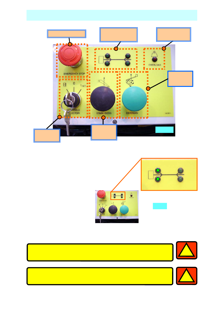
Check that each LED on the Ground Control panel is still illuminated. This in-
dicates that each foot is in firm contact with the supporting surface.
Fig. 5
Motor Run
Booms
Motor Run
Outriggers
Control
Selector
Cage Overload
Indicator
Outrigger Load
Indicators
Emergency Stop
- A46JRT (28 pages)
- A62JRT (26 pages)
- AB38-sn3700-04243 (20 pages)
- AB38-sn4500+ (20 pages)
- AB38-sn04244+ (20 pages)
- AB46-sn1000+ANSI (6 pages)
- AB46 Bi Energy and Electric (12 pages)
- AB46 Bi-Energy (46 pages)
- AB46 Electric-sn1000+CE (48 pages)
- AB46 Electric-sn1000+ANSI (12 pages)
- AB46E (22 pages)
- AB46JE (62 pages)
- AB46JRT (68 pages)
- AB46RT-sn1000+ANSI (16 pages)
- AB46RT-sn1000+CE (48 pages)
- AB46RT-sn10000 (22 pages)
- AB48HSRT-sn4611+ (32 pages)
- AB48HSRT-sn4633 (32 pages)
- AB50JRT (90 pages)
- AB60JRT-sn10000+ (122 pages)
- AB62 (24 pages)
- AB62RT (48 pages)
- AB85RJ (71 pages)
- LX31 Electric-sn3300 - 4021 (12 pages)
- LX31-sn1001-2746 (40 pages)
- LX31 Electric-sn4022+ (104 pages)
- LX31 Electric-sn4022-4390 (20 pages)
- LX31 Electric-sn1879-4274 (24 pages)
- LX31 Electric-sn4275+ (64 pages)
- LX31-sn2747-3299 (40 pages)
- LX31-sn3300-4021 (12 pages)
- LX31-sn4022+ (24 pages)
- LX31-sn4275+ (72 pages)
- M1230E (20 pages)
- M2032J (84 pages)
- M2639J-sn1000-1199 (31 pages)
- M2639J-sn350+ (82 pages)
- MB26-sn0001-0244 (16 pages)
- MB20 (32 pages)
- MB20N-sn132+ (132 pages)
- MB26-sn245+ (132 pages)
- MB26-sn435-999 (30 pages)
- MB26-sn1000+ (32 pages)
- MX15-sn1004-1599 (8 pages)
- MX15-sn12900-13999 (8 pages)