Snorkel Bi-Energy-sn1879-4274 User Manual
Page 4
4
2. Turn controller key switch clockwise to ON.
3. Position drive/lift switch to DRIVE position. Drive
enable indicator will be illuminated.
4. With the speed range switch first in LOW SPEED
and then again in HIGH SPEED depress the interlock
lever and slowly push the control lever to FORWARD
then REVERSE positions to check for speed and
directional control. The farther you push or pull the
control lever the faster the machine will travel.
5. Push steering switch RIGHT then LEFT to check for
steering control.
6. Hook controller on guardrail in original position.
7. Turn the platform/chassis switch to CHASSIS.
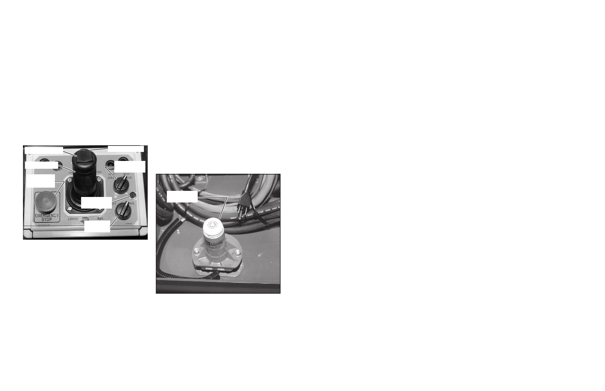
8. From lower controls, push chassis raise button to
elevate platform while pushing the tilt sensor (Figure 3)
off of level. The platform should only partially elevate
and the tilt alarm should sound. If the platform contin-
ues to elevate and/or there is no alarm STOP and
remove the machine from service until it is repaired.
9. Release the tilt sensor and fully elevate platform.
10. Visually inspect the elevating assembly, lift cylinder,
cables and hoses for damage or erratic operation.
Check for missing or loose parts.
11. Lower the platform partially by pushing in on the
chassis lower switch, and check operation of the
audible lowering alarm.
12. Open the chassis emergency lowering valve
(Figure 4) to check for proper operation by pulling
and holding the knob out. Once the platform is fully
lowered, close the valve by releasing the knob.
13. Turn the platform/chassis switch to PLATFORM.
14. Mount the platform making sure the gate is latched.
15. Position drive/lift switch to LIFT.
16. Depress the interlock lever and slowly push the
control lever to RAISE to raise the platform, fully
actuate the control lever to check proportional lift
speed. Elevate the platform to 3.7 m (12 feet).
17. Slowly pull control lever to DOWN position to lower
platform. Check that lowering alarm sounds.
18. Turn controller key switch to OFF, push the emergency
stop button and dismount the platform.
19. Close and secure module covers.
Figure 2: Controller
Interlock Lever
Lift/Drive
Switch
Emergency
Stop Switch
Steering Switch
Control Lever
Drive Enable
Indicator
Speed Range
Switch
Figure 3: Tilt Sensor
Tilt Sensor
45