312 activating "test, 12 activating "test" -15, 12 a – Snorkel LX41 Electric-sn4022+ User Manual
Page 85: Test, Mos90, Ctivating
Section 3 - Troubleshooting
Activating "TEST"
067448-003 LX31/LX41 Electric Work Platform
Page 3-15
3-12 A
CTIVATING
"TEST"
Position red LED at TEST. Press "+" or "-" to select the switch to be viewed.
The zero position input "-" should read zero and is set by adjusting the sensitivity threshold trim pot in the
upper control box. Step on the foot switch and keeping the Control Handle centered, adjust the pot to give
a readout of 1 or 2. Slowly back the pot down until the reading has just dropped to zero.
Connect voltmeter between B- and pin 14 on MOS90. Voltage at pin 14 in neutral should not be lower
than +3.5 volts D.C. 3.5 VDC = 0% speed input, 0.0 VDC=100% speed input.
If set at an extremely high value MOS90 will read as fault and shut down.
Properly set the LX31/41 should start to move slowly with a small movement of the Control Handle after a
very small "deadband" zone.
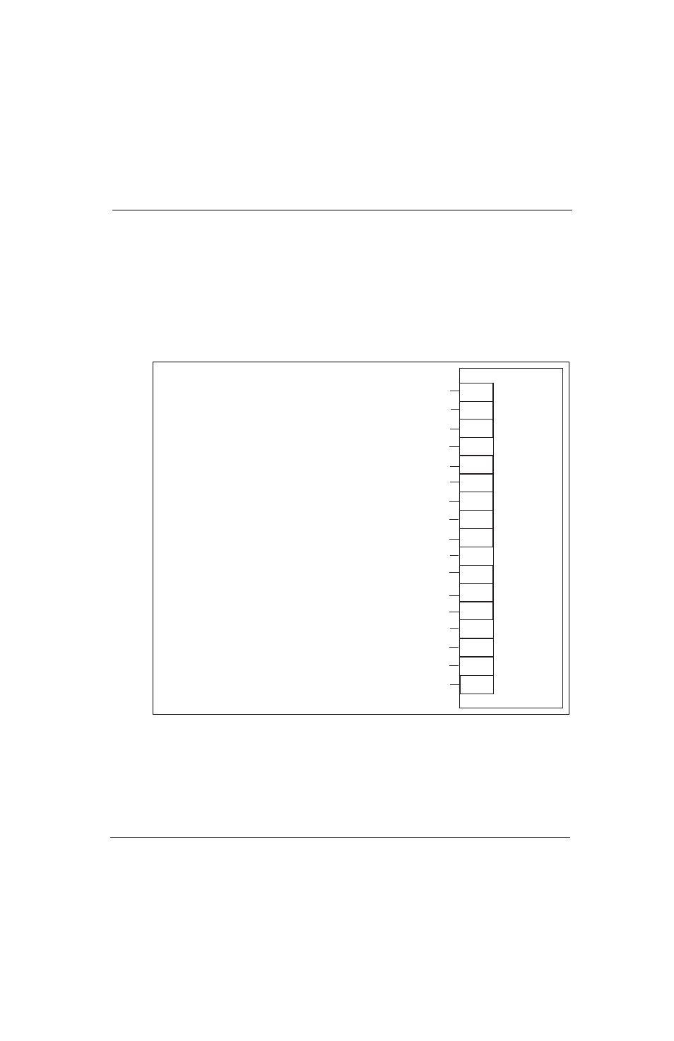
Figure 3-2: MOS90 17 Way Connector Pinout Designation
MOS90
1
2
3
4
5
6
7
8
9
10
11
12
13
14
15
16
17
Pump/Traction
Tachometer direction input from tach board
18 Volts = REV.
0 Volts = FWD.
No connection
Height Limit
Battery + side of direction & brake contactors for coil suppression (48 Volts)
+ 48 Volt supply to power up controller
Tilt
48 Volts when forward is selected & 0 Volts in neutral
No connection
No connection
48 Volts when reverse is selected & 0 Volts in neutral
Tach signal from tach gen.
7.5 Volts to 15 Volts = FWD. 0-100%
7.5 Volts to 0 Volts = REV. 0-100%
High/Low Speed
Traction accelerator signal (3.5 Volts to 0 Volts = min. to max. speed)
Forward contactor driver - goes to battery negative to energize contactor
Brake applied input
48Volts = brake on
0 Volts = brake off
Reverse contactor driver - goes to battery negative to energise contactor
Black
Brown
Red (spare)
Orange
Yellow
Green
Blue
Purple
Grey (spare)
White (spare)
Pink
White/Purple
White/Red
White/Black
White/Yellow
White/Blue
White/Green