Level sensor -16 – Snorkel LX41 Electric-sn4022+ User Manual
Page 54
Switch Adjustments
Section 2 - Service and Repair
Page 2-16
067448-003 LX31/LX41 Electric Work Platform
P
ROXIMITY
S
WITCH
H
EIGHT
A
DJUSTMENT
- S
ERIAL
N
UMBER
4275-C
URRENT
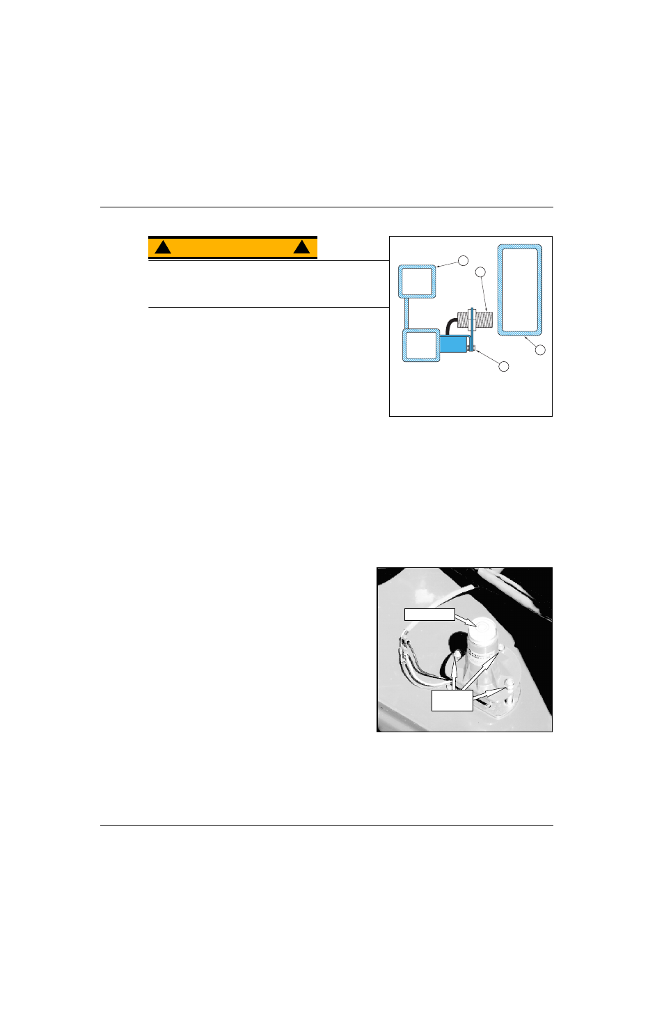
Figure 2-10: Proximity Switch Adjustment
W A R N I N G
!
!
Never perform service while the platform is elevated without
first blocking the elevating assembly.
DO NOT stand in the elevating assembly area while
deploying or storing the maintenance brace.
1. Place the machine on a firm, level surface.
2. Use an Inclinometer to ensure that the chassis is level
from front to rear and side to side.
3. Measure and record the distance from the top of the chas-
sis to the base of the work platform.
4. Elevate the work platform until the red LED at the rear of
the Proximity Switch turns OFF.
5. Measure the distance from the top of the chassis to the
base of the work platform and compare with Step 3..
• If the platform elevated 50 - 60 cm (1.75 - 2 ft.) no adjustment is necessary. Otherwise, continue.
6. Deploy the maintenance brace (see “Blocking The Elevating Assembly” on page 2-8).
7. Place a reference mark on the bracket to establish its position.
8. Loosen the bracket adjustment screws and move the switch up to increase or down to decrease platform
height. Tighten the adjustment screws.
9. Store the maintenance brace and fully lower the platform.
10. Repeat Step 4. and Step 5..
L
E V E L
S
E N S O R
Figure 2-11: Level Sensor
The Level Sensor has three wires;
• red-power in (12v),
• black-ground,
• white-power out (12v).
To verify the sensor is working properly there is one red
LED under the sensor. When the LED is ON, the sensor
is out of level, turning OFF the power to the white wire.
1. Check tires for proper pressure.
2. Place the machine on a firm level surface.
3. Use an inclinometer to ensure that the front and rear of
the Chassis are level.
4. Open the control module door to gain access to the
Level Sensor.
5. Adjust the three leveling locknuts until the bubble is
centered in the circle on the attached bubble level.
6. Deploy the maintenance brace (see “Blocking The Elevating Assembly” on page 2-8).
7. Push the Level Sensor base to test the alarm circuit. The red LED under the Level Sensor should turn
ON and the alarm should sound.
4
1
2
3
1. Proximity Switch
2. Bracket Adjustment Screws
3. Inner Assembly Arm Tube
4. Chassis
Bubble Level
Adjustment
Screws