Snorkel LX41 Electric-sn4022+ User Manual
Page 53
Section 2 - Service and Repair
Switch Adjustments
067448-003 LX31/LX41 Electric Work Platform
Page 2-15
R
EMOVAL AND
I
NSTALLATION
, S
ERIAL
N
UMBER
4275-C
URRENT
W A R N I N G
!
!
Never perform service while the platform is elevated without first blocking the elevating assembly.
DO NOT stand in the elevating assembly area while deploying or storing the maintenance brace.
1. Place the machine on a firm, level surface.
2. Use an inclinometer to ensure that the chassis is level from front to rear and side to side.
3. Deploy the maintenance brace (see “Blocking The Elevating Assembly” on page 2-8).
4. Disconnect the switch leads.
5. Remove the defective switch and install a new one.
6. Adjust the switch to elevating assembly tube clearance (see “Proximity Switch Clearance Adjustment -
Serial Number 4275-Current” on page 2-15).
7. Connect the switch leads.
8. Store the maintenance brace and lower the platform.
9. Adjust the Proximity Switch height (see “Proximity Switch Height Adjustment - Serial Number 4275-Cur-
P
ROXIMITY
S
WITCH
C
LEARANCE
A
DJUSTMENT
-
S
ERIAL
N
UMBER
4275-C
URRENT
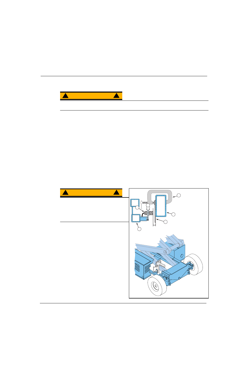
Figure 2-9: Proximity Switch Clearance Adjustment
W A R N I N G
!
!
Never perform service while the platform is
elevated without first blocking the elevating
assembly.
DO NOT stand in the elevating assembly area
while deploying or storing the maintenance
brace.
1. Place the machine on a firm, level surface.
2. Deploy the maintenance brace (see “Block-
ing The Elevating Assembly” on page 2-8).
3. Use an Inclinometer to ensure that the
chassis is level from front to rear and side to
side.
4. Use a clamp to attach a straight guide to the
elevating assembly tube.
5. Measure the distance from the face of the
Proximity Switch to the side of the guide
that faces the elevating assembly tube.
6. Turn the adjusting nuts to set the clearance
to 9,5 mm (0.375 in.) maximum.
7. Remove the clamp and guide and repeat
Step 5. and Step 6. of “Test the Proximity
Switch, Serial Number 4275-Current” on
page 2-14).
3
1
2
9,5 mm
(3/8 in.)
maximum
4
5
6
1. Proximity Switch
2. Clearance
Adjustment Nuts
3. Clamp
4. Guide
5. Inner Elevating
Assembly Tube
6. Chassis